
- Catalogs
- Marshalls plc
- Linear Drainage Design Guide www.marshalls.


Linear Drainage Design Guide www.marshalls.

Linear Drainage Design Guide www.marshalls.
Marshalls is committed to sustainability, targeting an 80% reduction in CO2 emissions by 2050. They have assessed the carbon footprint of over 500 products, verified by The Carbon Trust. The company also focuses on reducing water and waste, reports annually, and fosters community relations.
Marshalls ensures product compliance with industry standards and provides project-specific support. They offer reliable logistics and have invested in low-carbon transport, monitored by a customer service scoring system.
As the UK's leading hard landscaping company, Marshalls invests in its brand, products, and people to meet social and environmental requirements.
Marshalls aims for sustainable growth with high social responsibility, complying with legal standards and industry practices. Their management systems are audited by the British Standards Institution.
Marshalls conducts ethical risk assessments for non-UK sourced products and is a member of the Ethical Trading Initiative and UN Global Compact.
The guide details various drainage systems like Beany® Block, Mini Beany®, Max-E-Channel, and others, categorized by load classes from A15 to F900, suitable for different traffic and load conditions.
Linear drainage is preferred for its efficiency in intercepting water, shallow construction, ease of design and installation, cost savings, and reduced maintenance. It offers aesthetic options and better end-user comfort.
The guide outlines a procedure for selecting the appropriate drainage system based on location, capacity, and other site-specific parameters. It includes steps for determining channel location, length, and load classification.
The document provides guidelines for designing linear drainage systems, focusing on hydraulic design principles, system capacity, and practical considerations for installation and maintenance.
- Channel Systems: Various channel systems like Birco Lite, Landscape Drain, and Birco 100 are recommended for small paved areas. For larger areas, options include high-capacity systems like Max-E-Channel or Birco 300, and medium-capacity systems like Birco 100 with multiple outfalls.
- Loading Classifications: Defined by BS EN 1433: 2002, classifications range from Class A15 for pedestrian areas to Class F900 for areas with high wheel loads like aircraft pavements.
- Hydraulic Design: Involves assessing peak run-off and system capacity. Methods include the Simple Area Run-Off Method and the Modified Rational Method, which consider factors like area size, rainfall intensity, and storm profiles.
- System Capacity: Flow capacity is determined using traditional methods like the Colebrook-White formulae, with adjustments for continuous lateral inflow and shallow gradients.
- Maintenance: Regular maintenance is crucial, especially for systems with shallow gradients to prevent silting.
- Existing Drainage and Ground Levels: These factors influence the location of outfalls and the design of the drainage system.
- Outfalls: The location and capacity of outfalls can affect system efficiency.
- Inbuilt Fall Channels: These channels increase flow capacity and are beneficial in flat areas or where architectural details require specific pavement levels.
- Prime Incremental Depth: Channels are available in increments to accommodate various depth requirements.
- Manual Handling: Cured concrete is non-hazardous but requires proper handling techniques to avoid injuries.
- Mechanical Handling: Recommended for installing drainage components to improve efficiency and reduce manual labor.
- Weather Conditions: Installation should be paused during adverse weather to ensure quality.
The document discusses the use of cast iron in drainage systems, highlighting two types: grey iron and ductile iron. It mentions that the type of iron does not affect performance for the intended use. A temporary bitumen-based coating is applied to the cast iron, which is not meant for long-term protection and will wear off, leading to surface oxidation. The document explains that the oxidation process forms a protective silica layer that prevents further corrosion.
It emphasizes the importance of wearing Personal Protective Equipment (PPE) such as goggles, ear protection, dust masks, and protective footwear during cutting operations. COSHH data sheets are available for health and safety information.
Marshalls offers a free Drainage Design Service to ensure the correct system selection and installation. The design team provides support from conception to completion, using bespoke software to plan solutions. They assist with system selection, provide hydraulic data, and offer general advice.
The document lists various British Standards and other references related to drainage systems, concrete specifications, and construction details. These include BS EN 1433:2002 for drainage channels and BS EN 206-1:2000 for concrete specifications.
The Beany Block is a combined kerb and drainage system with a high capacity for stormwater storage. It is suitable for highway schemes, especially in flat areas, and offers cost savings over conventional drainage methods. The system is designed to minimize construction time and costs, with features that allow easy installation and maintenance.
The Beany Block system combines water interception and transportation, reducing the need for additional drainage components. It requires periodic inspection and maintenance, with fewer silt traps and outfalls compared to conventional systems. The system's design allows for easy retrofitting of pedestrian crossings and compatibility with other drainage systems like Max-E-Channel.
The document highlights the engineering benefits of the Beany Block system, including its high capacity, low maintenance, and cost-effectiveness. It is designed to withstand heavy vehicle loads and adverse weather conditions, with features that prevent blockages and ensure efficient water drainage.
The document outlines the specifications and installation procedures for the Beany Block system, a combined kerb and drainage system. It includes details on ancillary fittings and compatibility with standard detail drawings.
- The Beany Block system is made of pre-cast concrete and consists of top blocks with various profiles and base blocks of different depths (205/295/365/630mm).
- Components must comply with BS EN1433, Load Classification E600, and have specific water inlet aperture requirements.
- The system includes straight and radius cover plates, cable duct blocks, outfalls, silt traps, access covers, stop end top blocks, end caps, and sealant.
- Excavation: Ensure sufficient material is excavated for the installation of top and base units, concrete bedding, and haunching. Address any 'soft spots' or poorly compacted areas.
- Setting Out: Accurately locate setting out pins according to contract drawings. Use plenty of pins on horizontal curves and appropriate 'splay' units for radii of 50m or less.
- Mortar: Use class 12 cement mortar for bedding top blocks and Marshalls’ M-Flex for base block outfalls.
- Concrete: Use mix ST1 for normal kerb applications and mix ST4 for carriageway applications.
- All dimensions are in millimeters.
- Beany Block Access Covers and Frames are universal for both 'nearside' and 'offside' use.
- Movement joint details should isolate the Beany Block while maintaining restraint adjacent to concrete slabs.
The document provides detailed specifications for the installation of Beany Blocks, including the calculation of the number of blocks required for a quarter circle road junction. It specifies the use of concrete mixes ST1 and ST4 for different components and outlines the requirements for joint sealing with M-Seal bituminous mastic compound.
Instructions are given for laying Base Units and Top Blocks, starting from the Outfall and working uphill. The document emphasizes the importance of using a string line for alignment and checking levels with a spirit level. It also details the process for cutting units and the use of cement mortar for bedding.
The document references British Standards BS 8500-2 and BS EN 998-2 for concrete and mortar specifications. It recommends specific practices to prevent carriageway surface cracking and outlines the necessary precautions during construction to protect the units from damage.
The Mini Beany system is described as a versatile combined kerb and drainage system compatible with other Marshalls products. It includes various components such as Top Blocks, Base Channels, and Access Covers, with specifications for different profiles and lengths.
Guidelines are provided for the installation of Cover Plates and the use of End Caps. The document also includes maintenance instructions, such as cleaning the Beany Block System with high-pressure water jetting and ensuring all drainage apertures are free from obstructions.
The document includes hydraulic data and flow capacity information for different configurations of the Mini Beany system, with equivalent pipe diameters provided for various base units.
The document outlines the specifications for the Mini Beany system, a combined kerb and drainage solution. It includes details on ancillary fittings and compatibility with standard detail sheets. The system is manufactured by Marshalls and complies with British Standard BS EN1433:2002, load classification E600.
The Mini Beany system consists of pre-cast concrete components, with some fitments in cast iron. It features a two-part system with top blocks and constant depth base units available in depths of 210, 260, 310, and 360 mm. The overall width is not less than 280 mm. Key specifications include:
- Water inlet apertures with a minimum divergence angle of 5° and an incline of at least 30° to the horizontal.
- Water inlet apertures must be within individual units and not within 100 mm of the unit's end.
- Construction depth from the top of the base channels to the surface must be at least 100 mm.
- Top Block must have an Unpolished Skid Resistance Value (USRV) exceeding 70.
- Minimum water inlet aperture area of 12,850 mm²/m.
The hydraulic data for the Mini Beany system includes flow capacity in liters per second (l/s) and velocity in meters per second (m/s). This data is calculated using spatially variable flow design principles for different base units (210, 260, 310, 360) and gradients.
The document provides detailed component codes and weights for various parts of the Mini Beany system, including top components, access covers, cover plates, base channels, and outfalls. Each component is listed with its respective weight and code.
The document includes standard details and drawings for the Mini Beany system, illustrating cross-sections, longitudinal elevations, and specific component dimensions. These drawings provide guidance on installation and integration with existing infrastructure.
Guidelines for mortar and concrete mixes are provided, specifying the types of mortar and concrete required for different components and applications. The document also outlines the use of Marshalls' M-Flex and M-Seal for bedding and sealing joints.
Additional notes emphasize the importance of movement joint details, concrete cover requirements, and the application of vertical joint sealant to all base units. All dimensions are specified in millimeters.
The document provides detailed instructions for the installation of the Mini Beany Combined Kerb and Drainage System, emphasizing adherence to specifications and standard detail sheets.
Excavation must accommodate Top Block and Base Units, concrete bedding, and haunching. Proper setting out with pins and string lines is crucial, especially on horizontal curves, to ensure accurate alignment.
Base Units should be laid according to carriageway channel levels and bedded on freshly mixed concrete or cement mortar. Joint sealant is applied during installation, and cutting of units should be minimized.
Top Blocks are set on cement mortar, ensuring close jointing and alignment. Surplus mortar should be removed, and deviations corrected.
Cover Plates are bedded on cement mortar and sealed with M-Tape. They must be protected during installation. Additional components like Outfalls and Silt Traps require specific installation methods to ensure watertight joints.
The Max-E-Channel system integrates with Beany Block Top Units, offering a robust drainage solution with various top unit materials and load classifications. It is suitable for a range of applications from pedestrian areas to highways.
The system is tested to various load classifications, with components available in concrete, reinforced concrete, cast iron, and in-laid units. Access covers and frames are designed for ease of maintenance.
Installation should not occur in adverse weather conditions, and all necessary PPE must be worn. The document outlines specific procedures for ensuring the integrity and performance of the drainage system.
The document provides specifications for the Max-E-Channel system, including ancillary fittings, and is compatible with Standard Detail sheets. It is intended for use with the Manual of Contract Documents for Highway Works.
The Max-E-Channel system includes various base units and top units made of concrete or cast iron. The document specifies the dimensions, weights, and codes for each component. The system is designed to handle different load classifications, with specific materials and construction methods outlined for each classification.
The document includes detailed hydraulic data for Max-E-Channel units with both cast iron and concrete tops. Flow capacity is measured in litres per second (l/s) and velocity in metres per second (m/s) across different gradients and lengths. Theoretical outfall capacities are also provided for various base units and outlet pipe diameters.
Standard construction details are provided, including cross-sections and plans for the installation of Max-E-Channel units. The document specifies the use of different types of mortar and concrete for bedding and surrounding the units, depending on the load classification.
Component codes and weights are listed for top units, base channels, transition units, and access covers. These components are available ex-stock and are essential for the assembly of the Max-E-Channel system.
Detailed notes are provided for the use of mortars, concrete, and sealants in the construction of the Max-E-Channel system. Specific instructions are given for the formation of outfalls, silt traps, and junctions, particularly for Base 630 applications.
The document serves as a comprehensive guide for the installation and specification of the Max-E-Channel system, ensuring compatibility with highway works and adherence to relevant standards.
- The Max-E-Channel is a linear drainage system made from pre-cast concrete, with certain components in cast iron or galvanized steel, manufactured by Marshalls.
- The system consists of top units made from various materials and base units with depths of 205/295/365/630mm, and an overall width of at least 430mm.
- Components comply with British Standard BS EN1433, with load classifications ranging from C250 to F900 depending on the material.
- The system provides a minimum water inlet aperture area of 11,200mm²/m.
- Installation requires a minimum construction depth of 150mm above the base unit.
- Excavation should accommodate the units, concrete bedding, and haunching, with any soft spots addressed.
- Base units are bedded on freshly mixed concrete or cement mortar, with specific concrete grades required for different load classifications.
- M-Seal bituminous mastic jointing compound is used for sealing joints between units.
- Top units are set on cement mortar, with alignment and levels checked during installation.
- Units should be laid with the top 5mm below the final pavement level.
- Ensure proper alignment using a string line and compacted mortar.
- Transverse and longitudinal joints should be formed as needed, with protection against material ingress during concreting.
- Outfalls, silt traps, and access covers should be constructed per standard details, ensuring watertight joints.
- Concrete haunching should be inspected and approved before proceeding.
- Adjacent construction should not commence within 3 days of jointing or haunching.
- Post-installation, the system should be cleaned with high-pressure water jetting.
- Installation should not occur in adverse weather conditions, particularly below specified temperatures.
- Appropriate PPE must be worn during installation, especially during cutting operations.
- The Traffic Drain is a robust composite slot linear drainage channel system suitable for highways, compatible with the Mini Beany system.
- Manufactured according to BS EN 1433: 2002, it features high loading classification F900 cast iron top units.
- Base channels are available in various depths, with components like silt boxes and outfalls designed for high capacity and flexibility.
- Flow capacity and velocity data are provided for different gradients and lengths, calculated using spatially variable flow design principles.
This document provides a comprehensive overview of the Traffic Drain system, including specifications, installation procedures, and standard details. The system is designed for efficient linear drainage and is compatible with various construction standards.
The Traffic Drain system is manufactured from pre-cast concrete and cast iron, adhering to BS EN1433:2002 standards with a Load Classification of F900. It consists of a two-part system with cast iron top units and base units of varying depths (210/260/310/360mm). The system's width is at least 280mm, and it features a water inlet aperture area of 10,200mm²/m.
Installation should follow the specified guidelines, ensuring proper excavation, setting out, and bedding of units. Concrete bedding and haunching should meet specific standards (C20/25, C25/30, or ST4 concrete). Jointing requires Marshalls’ M-Seal sealant, and top units should be laid with a 5mm gap below the final pavement level.
Key construction notes include ensuring proper alignment using string lines, forming transverse and longitudinal joints, and protecting drainage apertures during concreting. The system should be cleaned post-installation using high-pressure water jetting.
Installation should not occur in adverse weather conditions, and appropriate PPE must be worn during operations. The document also outlines specific requirements for M-Seal coverage based on base type.
The document also covers Slot Drain Duo and Mono systems, highlighting their suitability for heavy traffic areas and discreet drainage solutions. These systems offer single or double slot entries and are available in various depths to accommodate different pavement constructions.
The document provides a comprehensive overview of the Marshalls Slot Drain Duo Linear Drainage System, detailing its components, specifications, and installation procedures. It is designed for use in various environments, from pedestrian areas to motorway crossovers, and is compatible with Marshalls' range of paving materials.
The Slot Drain Duo system consists of a fabricated, galvanized steel slot drain top combined with a base channel unit. It includes single and double entry slot drains, access units for maintenance, and bespoke solutions for specific project demands. Base channels are available in lengths of 1000mm or 500mm, with options for inbuilt falls to enhance drainage capacity.
The system is a two-part structure with inverted T-shaped slotted steel top units bolted to precast concrete drainage channels. It complies with Load Classification E600 according to BS EN 1433:2002. The system features water inlet slots, stainless steel bolts, and galvanized steel edge angles.
Installation involves excavation, bedding channels on concrete or mortar, and ensuring alignment and level accuracy. Channels should be laid starting from the outfall, with precise cutting and joint sealing using M-Flex sealant. The document outlines specific requirements for haunching and joint formation.
The document includes detailed hydraulic data, providing flow capacity and velocity information for various channel types and gradients. This data is calculated using the Colebrook-White formulae.
Outfall units are specified for different pipe diameters and include features like silt boxes and access covers. Joint sealant application is crucial for ensuring system integrity, with specific guidelines for M-Flex sealant usage.
Post-installation, the system requires cleaning to remove obstructions, either by removing gratings or using high-pressure water jetting. Proper maintenance ensures the longevity and effectiveness of the drainage system.
The Marshalls Slot Drain Duo system is a robust and versatile drainage solution, suitable for a wide range of applications. Its detailed specifications and installation guidelines ensure effective performance and compliance with industry standards.
The document provides a comprehensive overview of the Marshalls’ Slot Drain Mono Linear Drainage System, including specifications, installation procedures, and component details. It is designed for effective surface water removal while blending aesthetically with surrounding paving.
The Slot Drain Mono system is a two-part linear drainage system consisting of inverted T-shaped slotted steel top units and precast concrete drainage channels. The system complies with Load Classification C250 as per BS EN 1433:2002. The top unit features a 10mm water inlet slot, which increases in size towards the bottom, and the drainage channels have an invert width of 100mm.
The system includes top units, constant depth and inbuilt fall channels, outfalls, access covers, T junctions, end caps, cap outlets, and sealants. The channels are available in various depths and are designed to improve flow rates and discharge capacity.
The document provides detailed hydraulic data, including flow capacity in litres per second and velocity in metres per second, calculated using the Colebrook-White formula. Theoretical outfall capacities are also provided for different outlet pipe diameters.
Installation should follow the provided specifications and standard detail sheets. Excavation must accommodate the drainage channels, concrete bedding, and haunching. Channels should be laid starting from the outfall, with precise alignment and level. Joint sealant is applied before fixing gratings, and the system should be cleaned post-installation.
The Landscape Drain system is designed for aesthetic integration with paving, featuring discreet top units with 6mm or 12mm slots. It is suitable for pedestrian areas and offers medium capacity drainage with a loading classification of D400.
The Marshalls’ Slot Drain Mono and Landscape Drain systems provide effective and aesthetically pleasing drainage solutions for various applications, ensuring compliance with relevant standards and offering flexibility in installation and design.
- Birco 300AS: Designed for high flow capacity, suitable for areas like aircraft pavements and industrial hardstandings. Compatible with Class F900 applications.
- Birco Shallow: Suitable for areas with restricted construction depth, compatible with Class E600 applications.
- Components: Includes channels, gratings, caps, and outfalls with specific weight and code details.
- Gratings and covers are secured using stainless steel bolts into threaded steel sockets.
- Installation requires specific torque settings for different Birco models (e.g., Birco 300 requires 100 Nm).
- F900: For areas with abnormally heavy wheel loads, such as aircraft pavements.
- E600: For private traffic areas with heavy wheel loads.
- D400, C250, B125, A15: For various pedestrian and vehicular areas with decreasing load requirements.
- Concrete bedding and haunching specifications vary based on load class requirements.
- Standard installation drawings provide guidance on concrete grades and dimensions.
- Ensure all gratings are tightened to specified torque upon installation.
- Regular maintenance may be required to address surface oxidation of cast iron gratings.
The document provides specifications for the Marshalls Birco Linear Drainage System, including its components and installation procedures. It is designed to comply with BS EN 1433:2002 standards and is suitable for various loading applications.
The Birco Linear Drainage System consists of pre-cast concrete channels with galvanized steel or cast iron gratings. The system is available in different sizes and load classifications (C250/D400/E600/F900). The channels have built-in falls and are designed to accommodate various flow capacities.
Marshalls’ M-Flex sealant is used for jointing adjacent channels and vertical joints. It ensures a secure seal and prevents leakage. The sealant should be applied before fixing the gratings.
Installation involves excavating sufficient material to accommodate the drainage channels and concrete bedding. Channels should be laid starting from the outfall, ensuring alignment and level accuracy. Concrete haunching should be applied after inspection and approval.
Outfall units should be constructed as specified, with appropriate concrete bedding and surrounding. Horizontal joints between sections should be sealed with M-Flex sealant.
The Decathlon system, made from Glass Reinforced Concrete (GRC), offers high flow capacity and is suitable for various applications. It includes Heelguard top units for aesthetic finishes and is cost-effective due to reduced run sizes.
The document includes detailed specifications for different channel systems, including dimensions and hydraulic data. It also provides installation details for various top units and base components.
The Marshalls Birco and Decathlon drainage systems are robust, compliant with industry standards, and suitable for a wide range of applications. Proper installation and maintenance ensure optimal performance and longevity.
Catalog excerpts

Linear Drainage Design Guide www.marshalls.co.uk/watermanagement
Open the catalog to page 1
Marshalls Responsible Sourcing Marshalls plc is the UK’s leading hard landscaping company. It has achieved that status through progressive product innovation and by demonstrating outstanding service levels to customers. Marshalls recognise that this privileged position will only be perpetuated by continuous investment in its brand, its products and its people. This enables Marshalls to meet the social and environmental requirements of Britain’s landscapes, helping to transform educational spaces for the better. Corporate Management Marshalls believes in conducting its business in a manner which...
Open the catalog to page 2
www.marshalls.co.uk/watermanagement Sales Office: 0845 3020400 Email: [email protected] Contents Introduction Beany® Block Mini Beany® Traffic Drain Slot Drain (Duo and Mono) Landscape Drain
Open the catalog to page 3
Email: [email protected] The Case for Linear Drainage 7 References and Further Reading 19
Open the catalog to page 5
CLASS B125 125kN TEST LOAD CLASS C250 250kN TEST LOAD CLASS D400 400kN TEST LOAD CLASS E600 600kN TEST LOAD Footways, pedestrian areas, car parks, car parking decks and similar areas used by light, slowmoving traffic. Kerb-sides, general parking areas and hard shoulders that extend to a maximum of 0.5m into the trafficked area. Carriageways of roads (including pedestrian streets and parking areas) catering for all legal roadgoing vehicles. Private traffic areas used by vehicles imposing particularly heavy wheel loads. Special areas of abnormally heavy wheel loads e.g. aircraft pavements. Mini...
Open the catalog to page 6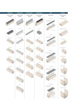
Traffic Drain Slot Drain Mono Landscape Drain Slot Drainage System Slot Drainage System Slot Drainage System Slot Drainage System Grid System Slot Drainage System Birco Lite Lite Cast Iron Grating 100 x 12mm slots Heelguard Top Unit Lite Channel 100 Cast Iron Grating 100 x 12mm slots In-Situ Lids 0/0 Birco 150 150 Cast Iron Grating 150 x 12mm slots 200 Cast Iron Grating 200 x 18mm slots Birco 300AS 300 Cast Iron Grating 125 x 20mm slots
Open the catalog to page 7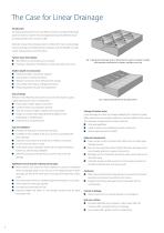
The Case for Linear Drainage Introduction The growing demand for more cost-effective and less complicated drainage systems has led to modern linear drainage becoming the preferred choice amongst specifiers and contractors alike. Marshalls’ unique linear drainage systems combine the clear-cut advantages of linear drainage over traditional point drainage, with the benefits of a high quality, robust precast concrete product. Surface water interception More efficient at intercepting running water Ponding is reduced or eliminated as is streaming water across a site Fig. 1 Typical point drainage system,...
Open the catalog to page 8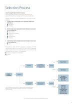
Selection Process Linear Drainage Product Selection Procedure The following pages describe the procedure for choosing the most appropriate Marshalls linear drainage system for a particular application. Marshalls’ comprehensive range of drainage systems can be split into three categories; 1. Combined Kerb and Drainage systems specifically designed for kerbside use; Beany Block Mini Beany 2. Slot Drainage Systems designed primarily (though not exclusively) for non-kerbside use; Max-E-Channel Slot Drain Duo and Mono Traffic Drain Landscape Drain Decathlon 3. Grid Drainage Systems designed primarily...
Open the catalog to page 9
Selection Process Channel Drainage Systems Five channel linear drainage systems are available from Marshalls, designed primarily (though not exclusively) for non-kerbside applications; Max-E-Channel High Capacity Linear Drainage System Birco Linear Drainage System Landscape Drain Slot Drain Traffic Drain Decathlon Step 4 If the channel length is well in excess of 60m, refer to the Max-E-Channel range page 59 and Birco 300 page 101. Choose either a large capacity system with few outfalls or a medium capacity system with more outfalls (See note 2). Step 5 Determine the load classification of the...
Open the catalog to page 10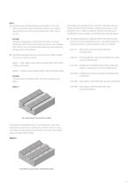
Notes 1) Generally, where the linear drainage channel length is in the order of 60m, one centrally located outfall will be sufficient and a medium capacity system such as Birco Lite, Landscape Drain or Birco 100 can be used. Example A relatively small paved area of dimensions 50 x 50m can be easily drained by a 100mm wide channel system such as Birco Lite, Landscape Drain or Birco 100. One centrally located outfall to suit the existing main drainage system will be sufficient. This example shows typically two Birco Lite, 100 or Landscape Drain runs utilising in-built fall channels, with four outfalls...
Open the catalog to page 11
Design Principles Introduction The basis of hydraulic design of any linear drainage system is fundamentally like any other engineering analysis; an assessment is made of the required performance level that the element has to achieve and this is compared to the element’s ability to accommodate this. In the case of linear drainage, how much water (peak run-off) will be flowing down the channel compared to the maximum stated flow capacity of the channel for the given conditions without causing any problems such as flooding. There are therefore two elements to any linear drainage design; a determination...
Open the catalog to page 12
Other Considerations There are other aspects of linear drainage design beyond the factors given above. These include: Maintenance All surface water collection and transport systems will require maintenance to ensure efficient performance. Where linear drainage is designed for shallow gradients due care must be taken in the design for the effects of silting. Many systems are kept free from silting by the action of fast flow, but HR Wallingford’s research confirmed that velocities flows as low as 0.4m/s “caused silt to move”. Existing Drainage The location of existing drainage systems may often...
Open the catalog to page 13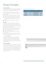
Design Principles Drainage Arrangements Due to the manufacturing flexibility available to Marshalls, we are able to offer several of our linear drainage and combined kerb and drainage systems with pre-sloped or inbuilt fall channels or base units. The inherent flexibility of inbuilt fall systems gives the designer a number of options to increase the flow capacity of the drainage run as circumstances dictate: Constant depth invert channels can be laid flat, or to a slope to increase the flow and discharge capacity (Figs. 8 & 9 opposite). Channels with progressively deeper inverts can be introduced...
Open the catalog to page 14All Marshalls plc catalogs and technical brochures
 Ascella_Granite_datasheet
3 Pages
 Altair_Granite_datasheet
3 Pages
 CPD BROCHURE
20 Pages
 WELL BEING
12 Pages
 COMMERCIAL CARBON FOOTPRINTS
20 Pages
 PRODUCT SELECTOR 3.1
124 Pages
 PRODUCT SELECTOR 3.0
381 Pages
 Permeable Paving Design Guide
70 Pages


- Industrial tile
- Indoor tile
- Floor tile
- Matte tile
- Outdoor tile
- Polished tile
- Public bench
- Contemporary public bench
- Rainscreen cladding
- Wooden public bench
- Public bench with backrest
- Stone tile
- Panel rainscreen cladding
- Embossed tile
- Industrial paver
- Garden tile
- Exterior paver
- Modular public bench
- Public space paver
- Smooth tile