WAAB-600
1 /46Pages

WAAB-600
1 /46Pages
Catalog excerpts

WAAB 600 Active hill d b A ti chilled beam – width 600 idth The WAAB-600 chilled beam is an air/water induction terminal unit that simultaneously provides the supply, thermal treatment and diffusion of supply air, to set internal conditions at the desired comfort levels. Chilled beams take advantage of the excellent thermal properties of water to guarantee optimal comfort levels, with minimal power consumption. The main heat-transferring component in the WAAB-600 chilled beam is a battery formed by copper battery, tubing and aluminium blades. It also incorporates air ducts and a plenum for supplying the ventilation air, which has been pre-treated in a central air conditioning unit. The WAAB-600 chilled beam can be supplied with connections on the side or on the top, for both supply air and return air. The unit can be adapted to modular ceilings measuring 600x600, 625x625 and 675x675 for T24 and T15 profiles. Thanks to its reduced size, it can also be installed in low-hanging false ceilings.
Open the catalog to page 1
1.-Air input neck 2.-Plenum 4 3.-Anchoring point for fixing 4.-Nozzles 5.-Adjustable deflector 6.-Collapsible front panel WAAB-600 Beam for supply air. …/2T/ 2 t b battery /2T/ 2-tube b tt …/4T/ 4-tube battery. …/LD/ Right side connection. …/LI/ Left side connection. …/S/ Top connection. …/ / Standard support …/T15/ Support for dropped panel, 15-mm profile modular ceilings. …/T24/ Support for dropped panel 24 mm /T24/ panel, 24-mm profile modular ceilings. …/KS/ Small discharge nozzles. …/KM/ Medium discharge nozzles. …/KL/ Large discharge nozzles. …/FC/ Front panel with circular perforations....
Open the catalog to page 2
CONSTRUCTION AND WORKING SYSTEM The ventilation air is injected through nozzles that cause the air to accelerate and force air induction in the room, through the battery. Subsequently, the two masses of air (the induced air and ventilation air) are supplied to the space that requires air-conditioning. Induced air The WAAB 600 has been designed so that it can be accessed easily for maintenance and servicing operations. For this, it has 4 fastening hinges, which keep the internal frame in position. Thus, the internal frame is collapsible over two axes, by simply moving the two hinges situated on...
Open the catalog to page 3
CONSTRUCTION AND WORKING SYSTEM Airflow adjustment The WAAB 600 chilled beam can be supplied with a primary airflow adjustment system. This adjustment can be made using a tube wrench with a diameter of 8 mm, making it easy to select between three air output configurations. Thus, even if the project specifications change, the primary airflow can still be readjusted using the same installation. Modification of the air deflection angle. The WAAB 600 chilled beam can be supplied with air deflectors situated over the internal frame. The deflectors can be adjusted individually over a range of 0 to...
Open the catalog to page 4
Circular side supply air connection. Circular top supply air connection . Left side. Circular side return air connection Cold water connection. Hot water connection. Circular top return air connection. Right side. The typological definition should indicate the type of configuration, followed by the nominal length (LN) and the total length (L1). E.g : LIR1 L1 x LN mm L1 = 895…2695 mm LN may only be supplied in standard lengths
Open the catalog to page 5
Configuration with side air connection Configuration with top air connection 406.8 1.- WAAB 600 dimensions table for LI, LD and S Configurations LI , LD and S L 1 (mm) min 895 1195 1495 1795 2095 2395 2695
Open the catalog to page 6
The Th WAAB 600 chilled b hill d beam i incorporates a series of mounting angle b k t on b th sides. t i f ti l brackets both id These brackets have an 18-mm long slot, so that the chilled beam can be easily mounted in the installation. The number of brackets available varies depending on the nominal length of the selected chilled beam; 4 for LN ≤ 1800 mm and 8 for LN ≥ 2100 mm. The unit should be suspended from the structure with officially approved steel supports, cables or rods. Once suspended, the primary air duct should be connected to the plenum’s neck. Likewise, the battery should be connected...
Open the catalog to page 8
Determining th D t i i the performance/characteristics of chilled beams properly requires the performance of both thermal and diffusion tests, based on the benchmarks of standards EN 15116, EN 13182 and EN 14240. mwc Ti,wc mwh Ti,wh To,wc To,wh The following diagrams show the characteristic curves for each of the models corresponding to the WAAB 600 product. The benchmark is as follows : 600 625 675 W N x LN Nominal length V H1 VL H1 B LN LWA P P pr Pw Pw,r m pr m wh m wc Tpr TR Ti,wc To wc o,wc Ti,wh To,wh Pa ∆P w ∆t aw Air speed at H1 height Air speed at L height Distance from ceiling to living...
Open the catalog to page 9
TECHNICAL DATA and METHODOLOGY Methodology A chilled beam’s capacity consists of one part supplied by the primary air and a second part supplied by the water. P = Ppr + Pw,r The primary air rate can be calculated using the Graphs numbered with II It can likewise II. be calculated using the following equation: Because of the chilled beams’ high capacity in heating mode, it is not necessary for the primary air to supply additional heat. In these cases, the system usually works with a g y g g primary air at the same temperature y p discharge of isothermal air, that is, by discharging the p as that...
Open the catalog to page 10
TECHNICAL DATA and METHODOLOGY Calculation 1.- Firstly, we determine the primary airflow volume for each of the chilled beams. Using Diagram IV on page 14, we select the type of nozzle depending on the maximum permissible noise level. Diagram IV: Nozzle KS → mpr=80 m3/h → LWA=41 dBA → Pa = 178 Pa g 2.- The chilled beam’s nominal cooling capacity is determined based on the primary airflow and the difference in temperature between the benchmark for the premises and the supply water (∆twa). To do this, we use diagrams V and VI. Diagram V and VI: Nozzle KS → mpr=80 m3/h → ∆taw=26 -16 = 10 ºC → Pw...
Open the catalog to page 11All MADEL catalogs and technical brochures
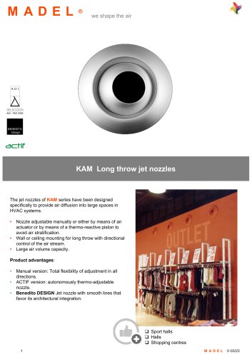 KAM
KAM6 Pages
 WAAB 4-WAY
7 Pages
 SCC
SCC11 Pages
 LMT-S
LMT-S4 Pages
 MADEL BMC
4 Pages
 MADEL AMT-AC
6 Pages
 TEO
TEO3 Pages
 LOOK
LOOK7 Pages
 KAP
KAP6 Pages
 TAU
TAU3 Pages
 UFA
UFA4 Pages
 LOF&LAIF
6 Pages
 DXL
DXL4 Pages
 DBQ
DBQ7 Pages
 SVA-R
SVA-R6 Pages
 KSP SUB
2 Pages
 KCA
KCA2 Pages
 KRC-PLUS-FREE-COOLING
4 Pages
 KBY
KBY3 Pages
 ZMARTBOX
4 Pages
 FOC-EIS-120
6 Pages
 FTR
FTR3 Pages
 FDS-MINI
3 Pages
 FSC-60
3 Pages
 WAAB-300
46 Pages
 FBK-EIS-120
11 Pages
 FOC-EIS-180
6 Pages
 FOC-EIS-90
5 Pages
 FOK-EIS-180
6 Pages
 INTERFACES
1 Page
 K1
K12 Pages
 KSP
KSP2 Pages
 KFC-PLUS
2 Pages
 KRC-PLUS
2 Pages
 SKP
SKP3 Pages
 SKC-C
SKC-C3 Pages
 SKC-R
SKC-R3 Pages
 SMS
SMS4 Pages
 SCC
SCC4 Pages
 SQR
SQR7 Pages
 CRG
CRG8 Pages
 RXO
RXO14 Pages
 AXP
AXP5 Pages
 AXO
AXO30 Pages
 FOK-EIS-120
6 Pages
 SVA-C
SVA-C3 Pages
 DCG
DCG12 Pages
 AX6
AX610 Pages
 PLAY
PLAY11 Pages
 ZONING SYSTEM CATALOGUE
20 Pages
Archived catalogs
 madel
madel9 Pages
 DCN circular diffusers
8 Pages


- Ventilation grill
- Metal ventilation grill
- Rectangular ventilation grill
- Industrial air diffuser
- Aluminum ventilation grill
- Square ventilation grill
- Ceiling-mounted air diffuser
- White ventilation grill
- Circular displacement air diffuser
- Square air diffuser
- Ventilation damper
- Linear air diffuser
- Metal ventilation damper
- Slot air diffuser
- Linear ventilation grill
- Round ventilation grill
- Industrial monitoring system
- Wall-mounted air diffuser
- Heating ventilation grill
- Galvanised steel ventilation grill