

- Company
- Products
- Catalogs
- News & Trends
- Exhibitions
Macalloy Compression Strut System Assembly
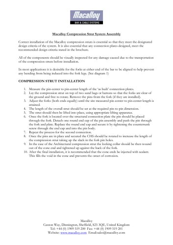
Macalloy Compression Strut System Assembly
- Inspect all components for damage from transportation.
- Ensure connection plates meet recommended design criteria.
- Measure the pin-center to pin-center length of the connection plates.
- Position the compression strut on sandbags or batons to allow fork rotation.
- Adjust forks equally to match the measured pin-center length.
- Set the strut to the required pin-to-pin dimension.
- Lift the strut into place using appropriate lifting equipment.
- Insert and secure pins through the fork and connection plate.
- Repeat for the second connection.
- Rotate the CHS to increase strut length and eliminate slack.
- For architectural struts, tighten the locking collar against the fork.
- Inject sealant into cone ends to prevent corrosion.
- Diagram 1: Illustrates correct and incorrect fork orientations, highlighting potential issues with bending moments and buckling effects.
- Diagram 2: Differentiates between architectural and standard compression struts.
Catalog excerpts
Correct installation of the Macalloy compression struts is essential so that they meet the designated design criteria of the system. It is also essential that any connection plates designed, meet the recommended design criteria stated in the brochure. All of the components should be visually inspected for any damage caused due to the transportation of the compression struts before installation. In most applications it is desirable for the forks at either end of the bar to be aligned to help prevent any bending from being induced into the fork legs. (See diagram 1) 1. Measure the pin-center to pin-center length of the ‘as built’ connection plates. 2. Lay the compression strut on top of two sand bags or battons so that the forks are clear of the ground and free to rotate. Remove the pins from the fork (if they are installed). 3. Adjust the forks (both ends equally) until the site measured pin-center to pin-center length is attained. 4. The length of the overall strut should be set at the required pin-to-pin dimension. 5. The strut should then be lifted into place, using appropriate lifting apparatus. 6. Once the fork is located over the structural connection plate the pin should be placed through the fork. Detach one round end cap of the pin assembly and push the pin through the fork and plate. Replace the round end cap and secure it by tightening the countersunk screw through the end cap and into the pin body. 7. Repeat the process for the second connection. 8. Once the pins are in place and secured the CHS should be rotated to increase the length of the compression strut taking up the slack in the fork pin holes. 9. In the case of the Architectural compression strut the locking collar should be then wound out of the cone end and tightened up against the back of the fork. 10. After the final installation, it is recommended that the cone ends be injected with sealant. This fills the void in the cone and prevents the onset of corrosion.
Open the catalog to page 1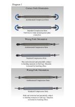
Diagram 1 Correct Fork Orientation Architectural Compression Strut Standard Compression Strut Fork free to rotate around gusset plate connection Wrong Fork Orientation Architectural Compression Strut Standard Compression Strut One end restricted and potentially subject to bending moment on fork legs. Situation worsened by buckling effect. Wrong Fork Orientation Architectural Compression Strut Standard Compression Strut Both end restricted and potentially subject to bending moment on fork legs. Situation worsened by buckling effect.
Open the catalog to page 2All Macalloy catalogs and technical brochures
 POST TENSIONING SYSTEM
12 Pages
 SHEET PILING SYSTEMS
8 Pages
 TENSION STRUCTURES
16 Pages


