- Catalogs
- LINEA LIGHT GROUP
- INK System
- Company
- Products
- Catalogs
- News & Trends
- Exhibitions
INK System
1 /60Pages

INK System
1 /60Pages
Catalog excerpts

Evolution and revolution! "A clean, precise sign of black ink. It may seem little; it actually becomes revolutionary when it conveys meaning, something much more important than the sign itself: a concept. That simple sketch is the essence of communication. If plotted logically, the ink transmits a message. If traced with grace, it embellishes the space and increases the value and the preciousness of the sheet as well as of what is written on it, whether it is an inscription or a drawing. INK System represents an evolution and at the same time a revolution in the lighting panorama: it revises...
Open the catalog to page 5
Designed to adapt to any architectural situation "Entirely designed and manufactured in Italy, INK is the perfect solution to overcome all the problems caused by preexisting incomplete electrical systems or environmental limitations: cramped spaces, valuable materials not affected, lack of an adequate number of light points, up to the impossibility of installing drivers remotely. In a nutshell: maximum versatility, in any surface and in any environment, even those with considerable installation limits. INK is not a single lamp declined in multiple versions, but a system that includes multiple...
Open the catalog to page 6
“Light profiles and linear suspensions with diffused emission or UGR controlled by special darklight cells, adjustable spotlights with three different optics and spot suspensions. The INK range includes many luminous articles with an ultra-fast coupling system to the rubber cable: just choose the preferred position, fix the luminaire by light pressure and screw in the safety dowels with the special Allen key supplied. The cable acts as a safe and reliable conductor does not require any special protection or installation measures and allows maximum freedom of positioning. Changing is very easy:...
Open the catalog to page 9
Stretching system
Open the catalog to page 10
“The INK System allows avoiding the installation limits due to the impossibility to have a light point on the ceiling, due to the lack of systems and corrugated lines or to the presence of valuable materials or not-corrodible structures, such as beams, barrel vaults or cross vaults, historical ceilings. The two articulated fasteners allow the cable to be stretched and connected to the wall in an aesthetically pleasing way, taking advantage of an existing light point placed at the desired height or going to prepare a power supply system that provides for a remote installation (from the socket...
Open the catalog to page 11
Use the cable cutter kit 81427 to prepare the cable for wall mounting and wiring. Loosen the screws with an Allen key, insert the end of the cable to be cut and close the screws. Make sure that the cable is firmly fixed inside the template. Proceed with the various cuts following the appropriate slots and acting vigorously with the extremity of the cutter blade. Once finished, pull out the cable now divided into four Strip off any excess rubber parts until the two steel cables, and the two red and black power cables are released. At this point, proceed with the cutting of the excess steel cables...
Open the catalog to page 12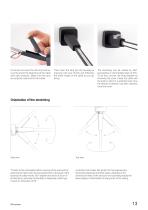
Unroll the roll, insert the LED strip and secure the end at the beginning of the cable with light pressure. Make sure the pins are properly inserted into the rubber. Then insert the strip into the housing by pressing with your thumb and following the entire length of the cable as you go along. The stretching can be rotated by 360° (proceeding in intermediate steps of 90°). To do this, uncover the fixing bracket by removing the cover, rotate the cable and the ends to which it is attached and, once the desired inclination has been reached, close the cover. Side view “Thanks to the articulated rubber...
Open the catalog to page 13
Stretching on plasterboard “The INK System provides the possibility of opting for installation on plasterboard thanks to the appropriate covers 81422. Basic requirement: the cable must be installed on masonry behind the plasterboard using a 81423 bracket. The designer must provide two 81422 covers for each plasterboard wall, which must be inserted into the cable before fixing; afterwards, once installed and under tension, create the dummy plasterboard wall (min. thickness 10 cm max. 25 cm) and position the spring-loaded covers in the cable entry and exit holes.
Open the catalog to page 14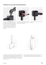
Stretching on masonry with decentralised light point The cover of the 81423 fixing bracket has three openings, originally closed but cuttable and detachable, arranged along three sides. Once the wall/ceiling path from power source has been prepared (p.20), it is necessary to connect it to the bracket by cutting the opening we are interested in and opening it with the help of a clamp. Fix the base of the bracket at the end of the cable, then proceed with the wiring and fixing of the steel cables. “Thanks to the versatility of the INK System, it is possible to feed the stretching product using...
Open the catalog to page 15
Wall/ceiling system
Open the catalog to page 16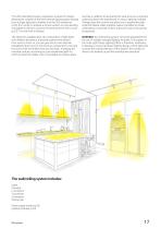
“The INK wall/ceiling system represents a praise for Design, allowing the creation of the most diverse lighting paths starting from a single light point, whether it be the 503 socket box (p.22) from which to prepare a remote system or a pre-existing corrugated to which to connect the external driver with a cover (p.23). The only limit is fantasy! line that, in addition to decorating the wall, acts as a conductor cable and allows the attachment of various lighting modules. Fittings close the corners and allow you to expand the path, while the flexible cable material makes it possible to create...
Open the catalog to page 17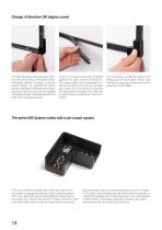
Change of direction (90 degree curve) To create the path, fix the extruded material to the wall or ceiling. The system allows orthogonal direction changes, using the various fittings. To calculate the correct position and distance between one extruded product and the next, use the supplied template and place it laterally between the ends of the extruded products. Once the extrusions have been arranged, position the cable sections properly cut. The rubber cable is then connected by inserting the hollow part into the extruded part, which acts as a rail. No accessories or fixing systems required....
Open the catalog to page 18All LINEA LIGHT GROUP catalogs and technical brochures
 Linealight Collection Volume 1
772 Pages
 Maestro_4_1_24
996 Pages
 Tablet-C15
2 Pages
 Rolling Sky
4 Pages
 News 2023
284 Pages
 Industrial & Urban Litingh 2021
346 Pages
Archived catalogs
 Ready To Go 2021
346 Pages
 Decorative 2023
412 Pages
 Maestro4.0.
996 Pages
 LLG MyWhite
16 Pages
 Arte & Culto
78 Pages
 Material & Design Lighting
364 Pages
 Maestro 2.0
1072 Pages
 STILNOVO meets MA&DE
188 Pages
 Fylo
Fylo99 Pages
 Indoor green
19 Pages
 Ready To Go 2020
290 Pages
 Decòrative News 2109
82 Pages
 Ready to Go 2109
216 Pages
 Decòrative Lighting
652 Pages
 MAESTRO Professional Lighting
932 Pages
 Home Lighting
564 Pages
 Architectural Lighting
666 Pages
 LLG Woofer
4 Pages
 LLG Arte & Culto
98 Pages
 Material & Design Lighting
350 Pages
 LLG Trail
24 Pages
 LLG Chlorophyll
8 Pages
 LLG Creek
25 Pages
- LINEA LIGHT indoor lamp
- LINEA LIGHT contemporary lamp
- LINEA LIGHT home lamp
- LINEA LIGHT corded lamp
- LINEA LIGHT metal lamp
- LINEA LIGHT LED lamp
- LINEA LIGHT single lamp
- LINEA LIGHT pendant lamp
- LINEA LIGHT white lamp
- LINEA LIGHT wall light
- LINEA LIGHT straight lamp
- LINEA LIGHT contemporary wall light
- LINEA LIGHT metal wall light
- LINEA LIGHT black lamp
- LINEA LIGHT light fixture
- LINEA LIGHT LED wall light
- LINEA LIGHT LED light fixture
- LINEA LIGHT round lamp
- LINEA LIGHT metal light fixture