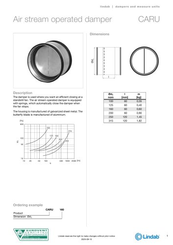
Catalog excerpts
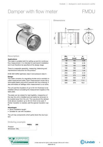
l indab | dampers and measu re u nits Damper with flow meter Description Applications The meter is suitable both for setting up and for continous flow measurement. It is intended for permanent installation and must therefore be specified at the design stage. There is a separate assembly, measuring, balancing and maintenance instruction for this product. Ø 80–630 fullfills tightness class 0 and pressure class A . Design The meter consists of a regulating shutter and a centrally located measurement plate. Each measurement nozzle has a removable plastic plug which prevents dirt from entering. It also eliminates air leakage when measurement is not done. The unit permits insulation of up to 50 mm thickness to be installed without concealing the measurement nipples or the label plate. The plate can be rotated for best legibility, irrespective of the way the unit is installed and can easily be removed, to be located away from the unit. The cup around the damper knob allows insulation up to 50 mm thick to be used. If thicker insulation is needed, add the special insulation cup IK. Advantages • Short installation length. • Suitable for use with insulation. The unit has components which partly block the duct system. Ordering example FMDU DUCT-MC Identification number 17.11.002 Lindab reserves the right to make changes without prior notice
Open the catalog to page 1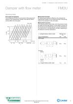
l indab | dampers and measu re u nits Damper with flow meter Technical data Flow graph for balancing The curves show the flow, q, as a function of the pressure difference in the measurement nozzles. Flow data for dimensioning differs from this graph. Measurement accuracy If the velocity profile is asymmetric, the measurement values can differ from the ideal values. For this reason, the flow meter should never be located right up to any flow disturbance. The method error in the table below will differ, depending on the distance to the flow disturbance. l1 =straight distance before meter...
Open the catalog to page 2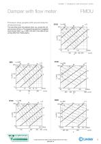
l indab | dampers and measu re u nits Damper with flow meter Pressure drop graphs with sound data for dimensioning The solid lines show the pressure drop, Δpt, across the unit as a function of flow, q. The dashed lines give the A-weighted sound power data, LWA, in dB to the duct. Flow data for balancing differ from these graphs. DUCT-MC Identification number 17.11.002 Lindab reserves the right to make changes without prior notice
Open the catalog to page 3
l indab | dampers and measu re u nits Damper with flow meter Ø250 500 DUCT-MC Identification number 17.11.002 Lindab reserves the right to make changes without prior n
Open the catalog to page 4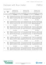
l indab | dampers and measu re u nits Damper with flow meter Sound generation Velocity app. 5 [m/s] dim Ød1 DUCT-MC Identification number 17.11.002 Lindab reserves the right to make changes without prior notice
Open the catalog to page 5All LINDAB catalogs and technical brochures
-
FSAFU
2 Pages
-
CARU
1 Pages
-
WK25
6 Pages
-
HV
2 Pages
-
LHUV
4 Pages
-
FNC1U
2 Pages
-
Lindab Inside
5 Pages
-
Stainless Duct Systems
2 Pages
-
Rainwater systems
16 Pages
-
Ventilation Product Range
8 Pages
-
Silent duct
2 Pages

