PIKO Sensor

PIKO Sensor
The document serves as the installation and operating manual for the PIKO Sensor by KOSTAL Solar Electric GmbH, providing comprehensive instructions for its installation, operation, and associated safety measures.
Legal Notice
It includes a legal notice prohibiting commercial use or modification of the manual without prior written permission from KOSTAL.
Notes on the Manual
Targeted at specialist tradespersons, the manual contains critical information on the installation and operation of the PIKO Sensor, emphasizing adherence to instructions to prevent damage or injury.
Proper Use
The PIKO Sensor is intended for measuring temperature, irradiation, and module temperature in photovoltaic systems, and should only be used with compatible PIKO inverters under specified conditions.
Symbols and Safety Instructions
Various symbols indicate warnings and important information, with warnings categorized by severity from 'DANGER' for life-threatening risks to 'ATTENTION' for potential property damage.
EU Declaration of Conformity
The PIKO Sensor complies with EU guidelines and standards, ensuring safety and electromagnetic compatibility.
Scope of Delivery
The package includes a PIKO Sensor, an adapter circuit board, and an operating manual.
Device and System Description
An overview of the PIKO Sensor's components and functions is provided, including sensors for irradiation, ambient temperature, and module temperature, along with connection cables.
Installation
Detailed instructions are given for fitting the sensors and aligning them correctly with solar modules for accurate measurements.
Electrical Connection
Procedures for connecting the PIKO Sensor to PIKO inverters are described, with an emphasis on safety due to high voltages.
Technical Data
The manual details the technical specifications of the PIKO Sensor, including measurement parameters, supply voltage, power consumption, sensor precision, calibration, and measurement range.
Conclusion
Tables detailing measurement ranges and conversion formulas for setting up the PIKO Sensor in the PIKO Solar Portal and PIKO Master Control conclude the manual.
Catalog excerpts

Smart connections. Installation and Operating Manual PIKO Sensor
Open the catalog to page 1
LEGAL NOTICE KOSTAL Solar Electric GmbH Hanferstrasse 6 79108 Freiburg i. Br. Germany Tel. +49 (0)761 47744-100 Fax +49 (0)761 47744-111 www.kostal-solar-electric.com General note on gender equality KOSTAL is aware of how language impacts on gender equality and always make an effort to reflect this in documentation. Nevertheless, for the sake of readability we are unable to use non-gender-specific terms throughout and use the masculine form instead. © 2012 KOSTAL Industries Electric GmbH. Subject to technical changes and printing errors. All rights reserved by KOSTAL, including those of reproduction...
Open the catalog to page 2
Thank you for choosing a PIKO Sensor from KOSTAL Solar Electric GmbH! If you have any technical questions, please call our service hotline: +49 (0)761 47744-222 1. Notes on this manual Read this manual carefully in its entirety. It contains important information on the installation and operation of the PIKO Sensor. Pay particular attention to the instructions regarding safe usage. KOSTAL Solar Electric GmbH assumes no liability for damages arising from the non-observance of this manual. This manual is an integral part of the product. It applies exclusively to the PIKO Sensor from KOSTAL Solar...
Open the catalog to page 4
Exclusion of liability All names, trademarks, product names or other designations given in this manual may be legally protected even if this is not labelled as such (e.g.as a trademark). KOSTAL assumes no liability for their free usage. The illustrations and texts have been compiled with great care. However, the possibility of errors cannot be ruled out. The ompilation is made without any guarantee. c Any instance of misuse of the PIKO Sensor will result in termination of the warranty, guarantee and general liability of the manufacturer. Only a qualified electrician may open the unit. The PIKO...
Open the catalog to page 5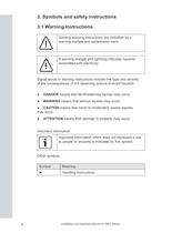
3. Symbols and safety instructions 3.1 Warning instructions General warning instructions are indicated by a warning triangle and exclamation mark. A warning triangle and lightning indicates hazards associated with electricity. Signal words in warning instructions indicate the type and severity of the consequences of not observing actions to avoid hazards. ●● DANGER means that life-threatening injuries may occur. ●● WARNING means that serious injuries may occur. ●● CAUTION means that minor to moderately severe injuries may occur. ●● ATTENTION means that damage to property may occur. Important...
Open the catalog to page 6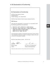
4. EU Declaration of Conformity EU Declaration of Conformity KOSTAL Solar Electric GmbH Hanferstrasse 6 79108 Freiburg i. Br., Deutschland KOSTAL Solar Electric GmbH hereby declares that the PIKO Sensor with which this declaration is concerned, is in accordance with the following guidelines and standards. EN ●● EN61010-1 (2011), EN61010-31 (2008) (Safety) ●● EN61326-1 (2006), EN61326-2-1 (2006), EN61326-2-2 (2006), EN 61326-2-3 (2007) (EMC) 2006 / 95 / EC + 2004 / 108 / EC This declaration applies to all identical specimens of the product. This declaration becomes invalid if a change is made...
Open the catalog to page 7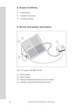
5. Scope of delivery ●● 1 PIKO Sensor ●● 1 adapter circuit board ●● 1 operating manual 6. Device and system description 2 3 1 4 Fig. 1 PV system with PIKO Sensor (1) PIKO inverter (2) Solar modules (3) Module temperature sensor (on rear of module) (4) Irradiation and ambient temperature sensor 8 Installation and Operating Manual for PIKO Sensor
Open the catalog to page 8
7. Overview of components 2 1 3 4 5 Fig. 2 Overview of components EN (1) Irradiation and ambient temperature sensor (2) Module temperature sensor (3) Connection cable (4) Adapter circuit board (for communication board II) (5) Mounting plate with hole 7.1 Function description of PIKO Sensor The PIKO Sensor measures the following parameters: ●● Irradiation ●● Ambient temperature ●● Module temperature The silicon sensors on the sensor housing cover measure irradiation. The sensors supply a voltage proportional to the level of irradiation. The sensor for ambient temperature is fitted directly in...
Open the catalog to page 9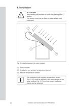
8. Installation ATTENTION Snow sliding off modules or roofs may damage the sensor! The sensor must not be fitted in areas where such risks exist. 2 3 1 Fig. 3 Installing sensor on solar module (1) Solar module (2) Irradiation and ambient temperature sensor (3) Module temperature sensor The irradiation and ambient temperature sensor (Fig. 3 (2)) must be aligned to the same angle as the solar module (Fig. 3 (1)) so that correct measurements can be obtained. 10 Installation and Operating Manual for PIKO Sensor
Open the catalog to page 10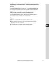
8.1 Fitting irradiation and ambient temperature sensor A mounting plate with an M10 hole (Fig. 2 (4)) is attached to the sensor housing to secure the sensor directly to the module substructure. 8.2 Fitting module temperature sensor The module temperature sensor sits in a foam adhesive pad so it can be stuck directly on to the rear of the module. Procedure ►Remove protective film from sensor's adhesive pad ► ►Apply sufficient pressure to stick module temperature sensor ► (Fig. 3 (3)) onto rear of module. ►Use cable clips to fix sensor cables without voltage. ► Installation and Operating Manual...
Open the catalog to page 11
9. Electrical connection 9.1 Connecting PIKO Sensor to PIKO inverter with communication board I PIKO inverters with communication board I have just one operating element (contact sensor) on their control panel. Fig. 4 Control panel of PIKO inverter with communication board I For more information, consult chapter "6.8 Installing accessories with communication board I" in the operating manual for the PIKO inverter. Procedure Electric current represents a danger to life There are deadly voltages in the inverter during operation. ►De-energise the inverter. ► ►Lock to prevent it being switched back...
Open the catalog to page 12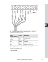
F/g. 5 Connecting PIKO Sensor's connection cable to analogue outputs of communication board I Tab. 1: PIKO inverter terminal connection assignment ► Screw down inverter cover. retaliation and Operating Manual for PIKO Sensor
Open the catalog to page 13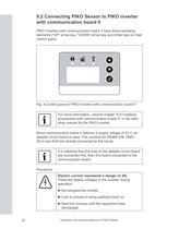
9.2 Connecting PIKO Sensor to PIKO inverter with communication board II PIKO inverters with communication board II have three operating elements ("UP" arrow key, "DOWN" arrow key and Enter key) on their control panel. Fig. 6 Control panel of PIKO inverter with communication board II For more information, consult chapter "6.9 Installing accessories with communication board II" in the operating manual for the PIKO inverter. Since communication board II delivers a supply voltage of 12 V, an adapter circuit board is used. The contacts for RS485 A/B, GND, S0‑in and Ain4 are directly connected to the...
Open the catalog to page 14All Kostal catalogs and technical brochures
 PIKO 10
2 Pages
 PIKO 12
2 Pages
 PIKO 15
2 Pages
 PIKO 17
2 Pages
 PIKO 20
2 Pages
 Data sheet PIKO 3.0
2 Pages
 PIKO Data Communicator
2 Pages
 PIKO M2M Service
1 Page


- Solar inverter
- PV inverter
- Multifunction sensor
- String inverter
- Industrial monitoring software
- Three-phase inverter
- Industrial monitoring system
- Transformerless inverter
- Single-phase inverter
- Wireless monitoring system
- Industrial datalogger
- Photovoltaïc installation monitoring system
- Residential installation inverter
- Uninterruptible power supply
- Photovoltaïc installation software
- Commercial uninterruptible power supply
- Data logger for PV applications