- Catalogs
- KOOLAIR S.A
- Variable volume terminal units – KS
Variable volume terminal units – KS
1 /32Pages

Variable volume terminal units – KS
1 /32Pages
Catalog excerpts
Variable volume terminal units
Open the catalog to page 1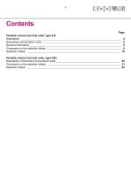
Contents Page Variable volume terminal units, type KS Description ____________________________________________________________________ 4 Dimensions and product code ______________________________________________________ 5 General information _______________________________________________________________ 6 Comments on the selection tables ___________________________________________________ 8 Selection tables ________________________________________________________________ 10 Variable volume terminal units, type KSL Description, dimensions and product code ____________________________________________...
Open the catalog to page 2
Variable volume terminal units, type KS Description Koolair boxes type KS are air volume control terminal units for use in single duct installations. KS boxes consist of a cabinet constructed of galvanised steel-sheet with interior thermal-acoustical insulation of fibreglass, fire resistance M1 not inflammable. They comprise of two connections, one circular or oval at the inlet and another rectangular at the discharge side. Also available is an additional plenum at the discharge side with various connections: circular, oval or rectangular, up to a maximum of five (see table on page 6). The volume...
Open the catalog to page 3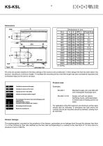
KS units are usually installed in the false ceilings of the rooms to be conditioned. In their design this fact has been taken into account, resulting in a minimum height. To facilitate the mounting of the units their length was also considered important and is therefore kept at 610 mm for all sizes. Indicate size from 100 to 8000. Re-heating coil with hot water. Electrical re-heating coil. Product code: Examples: KS-200-1 Standard supply unit, size 200 with one rectangular discharge duct. KS-200-7-P-W Supply unit with two lateral discharge ducts, perforated plate in interior and re-heating...
Open the catalog to page 4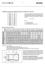
KS-KSL Coefficient to transform the differential pressure reading into air flow rate. Size In the following table the constants are presented which are used to calculate the air flow rate based on the differential pressure, measured by the probe situated in the inlet duct of the KS box, according to the following formula: Q = C •VPd Q = air flow rate in m3/h C = constant (see table) Pd = differential pressure at probe in Pa Comments: * Oval discharge. Maximum diameter lateral discharge: 315 mm. When lateral discharges are incorporated the length is 915 mm. For sizes 6000 and 8000 circular discharge...
Open the catalog to page 5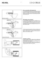
Duct connection discharge side The rectangular discharge can be connected to the duct as shown in the figure. In this way the exterior height of the duct is less than that of the KS and even permits exterior duct insulation without superseeding the height of the terminal unit. Detail duct connection Re-heating coil mounting In the standard configuration the re-heating coil is mounted at the discharge side of the KS unit on a 25 mm wide flange by means of screws. This way of mounting adds 50 mm to the height of the KS unit. The coil which is mounted in this configuration has a 60 mm pitch between...
Open the catalog to page 6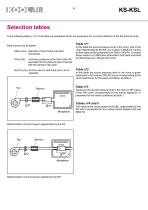
Selection tables In the following tables (1 to 10) all data are presented which are necessary for a correct selection of the KS terminal units. Data common to all tables: Diam.(mm): diameter of the circular inlet duct connection. Pmin (Pa): minimum pressure at the inlet of the KS, equivalent to the pressure loss of the box with the damper fully open. Q(m3/h) (l/s): Air flow rate for which the unit is to be selected. Reverberation room Determination of sound power regenerated by the KS. In this table the sound pressure level in the room is given expressed in NC (value of the NC curve corresponding...
Open the catalog to page 7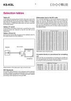
Table n°6 In this table the sound pressure level in the room, due to the noise radiated by the KS-unit, is given in dB(A) for various air flow rates and for pressures from 100 to 1000 Pa. To obtain these values a 10 dB/octave attenuation has been assumed for the false ceiling. Tables n°7 and 8 These tables are similar to the former, except that the sound pressure levels are referred to the NC and NR curves respectively. Tables n°9 and 10 Sound power levels (dB) are given for the radiated noise for the octave bands from 63 to 8000 Hz. Determination of the attenuation due to the KS units. ISO Standards All...
Open the catalog to page 8
KS-KSL Selection tables- Terminal units type KS (Sound pressure levels in dB(A)) KS Regenerated noise < : sound pressure level < 20dB(A)
Open the catalog to page 9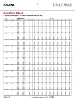
KS-KSLSelection tables- Terminal units type KS (Sound pressure levels in NC) KS UegOnRrated nEisA < : sound pressure level < NC 20
Open the catalog to page 10
KS-KSL Selection tables- Terminal units type KS (Sound pressure levels in NR) KS Regenerated noise < : sound pressure level < NR 20
Open the catalog to page 11
KS-KSLSelection tables- Terminal units type KS (Sound power levels in dB) ks RegoneraLNLnoise
Open the catalog to page 12
KS-KSL Selection tables- Terminal units type KS (Sound power levels in dB) KS RegeneratEd noisO
Open the catalog to page 13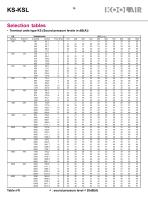
KS-KSLSelection tables- Terminal units type KS (Sound pressure levels in dB(A)) KS Radiated noise < : sound pressure level < 20dB(A)
Open the catalog to page 14
KS-KSL Selection tables- Terminal units type KS (Sound pressure levels in NC) KS Radiated noiAe < : sound pressure level < NC 20
Open the catalog to page 15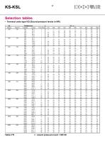
KS-KSLSelection tables- Terminal units type KS (Sound pressure levels in NR) KS Radiated Aoise < : sound pressure level < NR 20
Open the catalog to page 16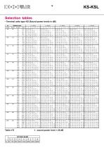
KS-KSL Selection tables- Terminal units type KS (Sound power levels in dB) KS Radiated noisD < : sound power level < 20 dB
Open the catalog to page 17
KS-KSLSelection tables- Terminal units type KS (Sound power levels in dB) KS Radiated noisD < : sound power level < 20 dB
Open the catalog to page 18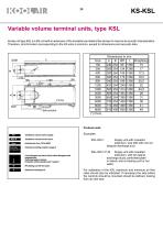
KS-KSL Variable volume terminal units, type KSL Koolar unit type KSL is a KS unit with an extension of the insulation part behind the damper to improve its acoustic characteristics. Therefore, all information corresponding to the KS units is common, except for dimensions and acoustic data. Indicate size from 100 to 8000. Indicate according to table on page 6 If not indicated, he interiorfinish will be fibreglass with neoprene film. Perforated plate in interior. Protection of the insulation with "melinex". Re-heating coil with hot water. Electrical re-heating coil. Product code: Examples: KSL-200-1 Supply...
Open the catalog to page 19All KOOLAIR S.A catalogs and technical brochures
 series FLOOR
23 Pages
 series Dampers 100-2
21 Pages
 FIRE protection
2 Pages
 KOOLCOM
2 Pages
 DFRE-P
1 Page
 PE-45
PE-451 Page
 Acoustic
2 Pages
 Series 100-200 Dampers
18 Pages
 VENTILATION HOODS
6 Pages
 Series SF Fire dampers
35 Pages
 Series SCDC Smoke dampers
11 Pages
 36-STE
2 Pages
 DTP-GT Multi-nozzles diffusers
15 Pages
 DTP Multi-nozzles diffusers
14 Pages
 Koolair product range
2 Pages
 Technical Selection Guide
145 Pages
 Bypass terminal units – KMSR
15 Pages
 Terminal units with fan – HVFS
12 Pages
 Air Volume Boxes – Series KD
7 Pages
 Measurement Station – EM
6 Pages
 Passive chilled beams – VPK
9 Pages
 Induction terminal units – IHK
20 Pages
 Square diffusers – Series 50
22 Pages
 Multinozzles diffusers – DF49MT3
20 Pages
 Long-throw nozzles – DF 89
19 Pages
 Long-throw nozzles – DF 49
19 Pages
 Linear grilles – Series 30
19 Pages
 S26
S261 Page
 21-DVC/21-DVR
1 Page
 21-SVC/21-SVR
1 Page
 20-SH/21-SH
1 Page
 20-DH/21-DH
1 Page
 Circular diffusers – DCL
2 Pages
 Extract valves – Series GPD
8 Pages
 Circular diffusers – Series 40.1
31 Pages
 Security grilles – KSG
12 Pages
 Return grilles – Series 20.2
19 Pages
 Supply grilles – Series 26
10 Pages
 Regulating dampers
18 Pages
 Silencers – Series SK
25 Pages
 Linear Diffusers – Series 70.1
26 Pages
 Circular diffuser – Series 40.1
31 Pages
 Supply grilles – Series 20.1
19 Pages


- Ventilation grill
- Metal ventilation grill
- Rectangular ventilation grill
- Industrial air diffuser
- Square ventilation grill
- Ceiling-mounted air diffuser
- White ventilation grill
- Home ventilation grill
- Circular displacement air diffuser
- Square air diffuser
- Interior ventilation grill
- Ventilation damper
- Air filter
- Linear air diffuser
- Adjustable ventilation grill
- Metal ventilation damper
- Slot air diffuser
- Linear ventilation grill
- Stainless steel ventilation grill
- Industrial jet nozzle