
Catalog excerpts

90-GV Variable geometry units
Open the catalog to page 1
S-90-GV Variable geometry unit CONTENTS Description and coding 2 Operation 3 Dimensions 4 Technical data 4
Open the catalog to page 2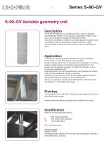
Description The S-90-GV diffusers are variable geometry units for installation at considerable heights. They consist of a perforated cylinder, inner discs, and a damper to change the discharge air flow. The unit is connected by means of a circular spigot in the upper cover. The diffusers may be suspended or fixed to columns or walls. They are made of galvanised steel sheet with built-in equalizing air discs. Application The S-90-GV variable geometry diffusers are used in industrial environments, in both heating and cooling systems. A built-in damper allows the air discharge to be changed...
Open the catalog to page 3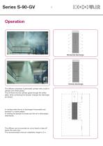
Horizontal discharge Vertical discharge The diffuser comprises a perforated cylinder with a built-in damper and orifice plates. The air flows into the cylinder guide through the orifice plate, when contacting the damper changes the discharge air stream. In cooling mode the air is discharged horizontally and spreads in a radial pattern. In heating the damper is closed and the air is discharged downwards. The diffuser can be mounted on a duct bend or take-off below the main duct. The recommended minimum installation height is 3 m.
Open the catalog to page 4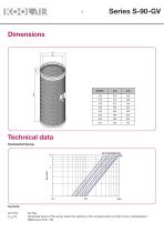
Technical data Horizontal throw. r Air flow Horizontal throw of the air jet, when the velocity in the occupied area is 0.20 m/s for a temperature difference of AT= -6K
Open the catalog to page 5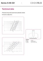
Technical data Pressure drop and sound level selection charts Horizontal configuration. Horizontal discharge Air flow Pressure drop Sound power lev
Open the catalog to page 6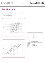
Technical data Pressure drop and sound level selection charts Vertical configuration. Air flow Pressure drop Sound power lev
Open the catalog to page 7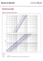
Ymax(m) Maximum vertical penetration depth for a temperature difference of AT
Open the catalog to page 8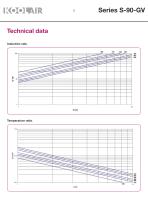
Technical data Induction rate. Temperature ratio.
Open the catalog to page 9
THIS CATALOGUE IS INTELLECTUAL PROPERTY. Partial or full reproduction of its content is strictly prohibited without the express written authorisation from KOOLAIR, S.A. CEN-S-90-GV-0415-00
Open the catalog to page 10
KOOLAIR, S.A. Calle Urano, 26 Poligono industrial nº 2 – La Fuensanta 28936 Móstoles - Madrid - (España) Tel: +34 91 645 00 33 Fax: +34 91 645 69 62 e-mail: info@koolair.com
Open the catalog to page 11All KOOLAIR S.A catalogs and technical brochures
-
series FLOOR
23 Pages
-
series Dampers 100-2
21 Pages
-
FIRE protection
2 Pages
-
KOOLCOM
2 Pages
-
DFRE-P
1 Pages
-
PE-45
1 Pages
-
Acoustic
2 Pages
-
Series 100-200 Dampers
18 Pages
-
VENTILATION HOODS
6 Pages
-
Series SF Fire dampers
35 Pages
-
Series SCDC Smoke dampers
11 Pages
-
36-STE
2 Pages
-
DTP-GT Multi-nozzles diffusers
15 Pages
-
DTP Multi-nozzles diffusers
14 Pages
-
Koolair product range
2 Pages
-
Technical Selection Guide
145 Pages
-
Bypass terminal units – KMSR
15 Pages
-
Terminal units with fan – HVFS
12 Pages
-
Air Volume Boxes – Series KD
7 Pages
-
Measurement Station – EM
6 Pages
-
Passive chilled beams – VPK
9 Pages
-
Induction terminal units – IHK
20 Pages
-
Square diffusers – Series 50
22 Pages
-
Multinozzles diffusers – DF49MT3
20 Pages
-
Long-throw nozzles – DF 89
19 Pages
-
Long-throw nozzles – DF 49
19 Pages
-
Linear grilles – Series 30
19 Pages
-
S26
1 Pages
-
21-DVC/21-DVR
1 Pages
-
21-SVC/21-SVR
1 Pages
-
20-SH/21-SH
1 Pages
-
20-DH/21-DH
1 Pages
-
Circular diffusers – DCL
2 Pages
-
Extract valves – Series GPD
8 Pages
-
Circular diffusers – Series 40.1
31 Pages
-
Security grilles – KSG
12 Pages
-
Return grilles – Series 20.2
19 Pages
-
Supply grilles – Series 26
10 Pages
-
Regulating dampers
18 Pages
-
Silencers – Series SK
25 Pages
-
Linear Diffusers – Series 70.1
26 Pages
-
Circular diffuser – Series 40.1
31 Pages
-
Supply grilles – Series 20.1
19 Pages


