- Catalogs
- KOOLAIR S.A
- Variable geometry diffusers – DGV
Variable geometry diffusers – DGV
1 /19Pages

Variable geometry diffusers – DGV
1 /19Pages
Catalog excerpts
DGV Variable geometry diffusers
Open the catalog to page 1
CONTENTS DGV variable geometry diffuser 2 Quick selection charts 5
Open the catalog to page 2
DGV variable geometry diffuser DIMENSIONS IN mm. Description DGV round, variable-geometry diffuser constructed of steel plate. The standard finish is RAL 9010 white paint. By special order, the diffuser can be painted in any RAL colour. Operation The DGV diffuser is composed of two concentric modules. The inner module is moveable, and can be moved manually or by a servo drive. This sliding inner module was designed such that, when moved, it simply and efficiently changes the direction of the outlet airflow. The flow direction may be horizontal (for cold air) or vertical (for hot air) as well...
Open the catalog to page 3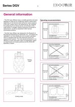
General information - The DGV-type diffusers have a variable geometry and were designed to meet the air conditioning needs of areas which, depending on the thermal loads during the various seasons of the year, require cold or hot isothermal air. By changing the positioning of an internal device, the direction of the outlet airflow is changed, thereby achieving a horizontal or vertical throw, as well as adjustment within several intermediate positions. - The DGV-type diffuser was designed by the Research & Development Department of KOOLAIR, S.A., and tested and calibrated in our own Distribution...
Open the catalog to page 4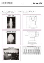
Photographs of DGV diffuser tests in the R&D Laboratory of KOOLAIR S.A. Plenum box for "DGV" diffuser (dimensions)
Open the catalog to page 5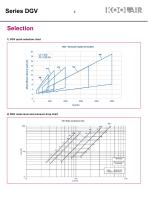
Series DGV Selection 1) DGV quick selection chart 2) DGV noise level and pressure drop chart
Open the catalog to page 6
Selection in a sample project Conditions • Hdif = 6.0 m • Hzo = 1.8 m • A = 5m • Q = 800m3/h • Ti = 35°C • AT = 15°C • Tr = 20°C • Lw < 40 dB (A) • P < 30 Pa • Vz = 0.25 m/s Symbols • Hdif = Distance from the supply mouth of the diffuser to the floor. • Hzo = Height of occupied area. • A = Distance between diffuser axes. • Q = Air flow in each diffuser. • Ti = Air supply temperature. • Tr = Room temperature. • AT = Difference between supply and room temperature. • Lw = Sound power. • P = Pressure drop. • Vz = Maximum velocity in occupied area. The above data are used for the selection, following...
Open the catalog to page 7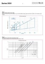
Step 1. Quick selection tips for the model Based on the flow rate and the distance, Hdiff, from the diffuser supply outlet to the floor, the 250 or 315 models can be chosen. Step 2. Verification by noise level and pressure drop. The data are obtained from the flow rate and the diffuser model.
Open the catalog to page 8
Comparison Thus, the charts indicate that the selected diffuser is DGV 315. Step 3. Determination of the temperature correction factor (Cy). It is necessary to know if the diffuser throw is within the operating limits. The next step (nº4) , is used to determine if the diffuser (in terms of throw) meets the needs required. This is determined by the temperature differenc ∆T (°C) and the maximum velocity in the occupied area. Vz (m/s), both specified in the conditions of the selection in the sample project. In this case, the factor «Cy» = 0,8 Step 4. Verification of throw within the operating limits....
Open the catalog to page 9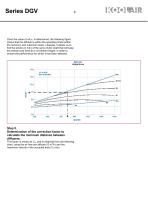
Once the value of «Ac», is determined, the following figure shows that the diffuser is within the operating limits (within the minimum and maximum lines). Likewise, it allows us to find the stroke (in mm) of the servo motor shaft that will keep the central core fixed at a convenient height, in order to ensure the performance for which it has been selected. Step 5. Determination of the correction factor to calculate the minimum distance between diffusers. This factor is known as Ca. and is obtained from the following chart, using the air flow per diffuser (Q m3/h) and the maximum velocity in the...
Open the catalog to page 10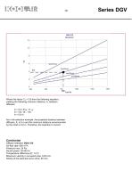
Series DGV Where the factor Ca = 3.8 from the following equation, yielding the following minimum distance, A, between diffusers: A = Ca / (Hdif - H zo) A = 3,8 / (6 - 1,8) A = 0,9 m As in the selection example, the projected distance between diffusers, A, is 5 m and the minimum distance recommended by the chart is 0.9 m. Therefore, the selection is correct. Conclusion Diffuser selected: DGV-315 Air flow rate: 800 m3/h Pressure loss: 24 Pa Sound power: 38 dB (A) Temperature difference AT: 15°C Maximum velocity in occupied area: 0,25 m/s. Stroke of the electrical servo drive: 50 mm.
Open the catalog to page 11
Selection charts to determine the factor, Ac (operating limits)
Open the catalog to page 12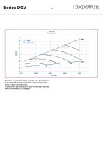
Where Ac is the vertical throw over the floor. The stroke (in mm) of the diffuser disc required to obtain the specified throw is shown on the curves. The minimum and maximum values are the limits between which the throw can be changed.
Open the catalog to page 14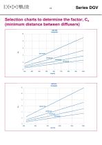
Selection charts to determine the factor, Ca (minimum distance between diffusers)
Open the catalog to page 15
Motor-driven operation The motor-driven operation system should be determined for each specific case. Please contact our Technical Department to carry out the respective study.
Open the catalog to page 17
THIS CATALOGUE IS INTELLECTUAL PROPERTY. Reproduction, either partial or total, by any means, including electronic, is prohibited without prior written authorisation from KOOLAIR, S.A. CEN-DGV-0815-00
Open the catalog to page 18
KOOLAIR, S.A. Calle Urano, 26 Poligono industrial nº 2 – La Fuensanta 28936 Móstoles - Madrid - (España) Tel: +34 91 645 00 33 Fax: +34 91 645 69 62 e-mail: [email protected]
Open the catalog to page 19All KOOLAIR S.A catalogs and technical brochures
 series FLOOR
23 Pages
 series Dampers 100-2
21 Pages
 FIRE protection
2 Pages
 KOOLCOM
2 Pages
 DFRE-P
1 Page
 PE-45
PE-451 Page
 Acoustic
2 Pages
 Series 100-200 Dampers
18 Pages
 VENTILATION HOODS
6 Pages
 Series SF Fire dampers
35 Pages
 Series SCDC Smoke dampers
11 Pages
 36-STE
2 Pages
 DTP-GT Multi-nozzles diffusers
15 Pages
 DTP Multi-nozzles diffusers
14 Pages
 Koolair product range
2 Pages
 Technical Selection Guide
145 Pages
 Bypass terminal units – KMSR
15 Pages
 Terminal units with fan – HVFS
12 Pages
 Air Volume Boxes – Series KD
7 Pages
 Measurement Station – EM
6 Pages
 Passive chilled beams – VPK
9 Pages
 Induction terminal units – IHK
20 Pages
 Square diffusers – Series 50
22 Pages
 Multinozzles diffusers – DF49MT3
20 Pages
 Long-throw nozzles – DF 89
19 Pages
 Long-throw nozzles – DF 49
19 Pages
 Linear grilles – Series 30
19 Pages
 S26
S261 Page
 21-DVC/21-DVR
1 Page
 21-SVC/21-SVR
1 Page
 20-SH/21-SH
1 Page
 20-DH/21-DH
1 Page
 Circular diffusers – DCL
2 Pages
 Extract valves – Series GPD
8 Pages
 Circular diffusers – Series 40.1
31 Pages
 Security grilles – KSG
12 Pages
 Return grilles – Series 20.2
19 Pages
 Supply grilles – Series 26
10 Pages
 Regulating dampers
18 Pages
 Silencers – Series SK
25 Pages
 Linear Diffusers – Series 70.1
26 Pages
 Circular diffuser – Series 40.1
31 Pages
 Supply grilles – Series 20.1
19 Pages


- Ventilation grill
- Metal ventilation grill
- Rectangular ventilation grill
- Industrial air diffuser
- Square ventilation grill
- Ceiling-mounted air diffuser
- White ventilation grill
- Home ventilation grill
- Circular displacement air diffuser
- Square air diffuser
- Interior ventilation grill
- Ventilation damper
- Air filter
- Linear air diffuser
- Adjustable ventilation grill
- Metal ventilation damper
- Slot air diffuser
- Linear ventilation grill
- Stainless steel ventilation grill
- Industrial jet nozzle