- Catalogs
- KOOLAIR S.A
- Series LK-70 Linear slot diffusers
Series LK-70 Linear slot diffusers
1 /33Pages

Series LK-70 Linear slot diffusers
1 /33Pages
Catalog excerpts

Linear slot diffusers BUREAU VERITAS Certification
Open the catalog to page 1
Technical data. Selection tables 9 Technical data. Selection graphs 11 Technical data. Selection tables 28 Technical data. Selection graphs 29
Open the catalog to page 2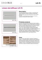
Linear slot diffuser LK-70 Description LK-70 linear supply diffuser for variable or constant flow rate, specially designed to maintain the ceiling or Coanda effect, including primary air flow rates reduced to 20% of the nominal flow rate. This diffuser made with aluminium frames has a 15-mm air passage, providing greater aesthetic appeal. Finished products Standard finished products are constructed of natural anodised aluminium or precoated with RAL-9010 gloss white. The directional blades can be adjusted by means of a drive wheel, which allows the air to be aimed in different directions up to...
Open the catalog to page 3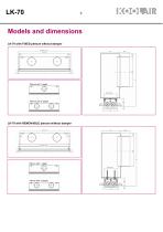
LK-70 with FIXED plenum without damper O Plenum with 1 spigot Plenum with 2 spigots LK-70 with REMOVABLE plenum without damper Plenum with 1 spigot G (OPENING) Plenum with 2 spigots
Open the catalog to page 4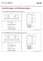
Ausführungen und Abmessungen LK-70 with FIXED plenum, with adjustable damper from the room OPENING= Plenum with 1 spigot G (OPENING) Plenum with 2 spigots Plenum box insulation by special order LK-70 with REMOVABLE plenum, with adjustable damper from the room Plenum with 1 spigot G (OPENING) Plenum with 2 spigots Plenum box insulation by special order
Open the catalog to page 5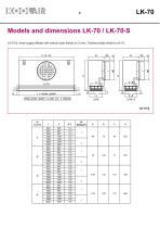
Models and dimensions LK-70 / LK-70-S LK-70-S, linear supply diffuser with narrow outer frames of 12 mm. Technical data similar to LK-70. FROM ACTIVE LENGTH >=1200 mm: 2 SPIGOTS
Open the catalog to page 7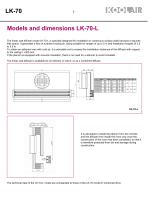
Models and dimensions LK-70-L The linear wall diffuser model LK-70-L is specially designed for installation in continuous surface walls because it requires little space. It generates a flow of turbulent mixing air, being suitable for ranges of up to 5 m and installation heights of 2.5 to 3.5 m. To obtain an adherent vein with cold air, it is advisable not to exceed the installation distances of the diffuser with respect to the ceiling h <300 mm. If the plenum is equipped with acoustic insulation, there is no need for a silencer to avoid crosstalk. The linear wall diffuser is available for air...
Open the catalog to page 8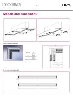
Models and dimensions SLOTS
Open the catalog to page 9
LK-70 Technical data. Selection tables LK-70 / LK-70-S LK - 70 VERTICAL DISCHARGE
Open the catalog to page 11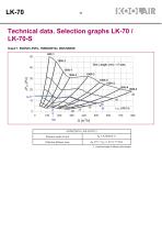
LK-70Technical data. Selection graphs LK-70 / LK-70-S Graph 1. SOUND LEVEL, HORIZONTAL DISCHARGE L = Nominal length of diffuser (active length)
Open the catalog to page 12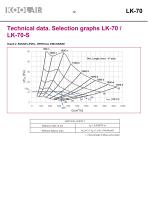
LK-70 Technical data. Selection graphs LK-70 / LK-70-S Graph 2. SOUND LEVEL, VERTICAL DISCHARGE L = Nominal length of diffuser (active length)
Open the catalog to page 13
Technical data. Selection graphs LK-70 / LK-70-S
Open the catalog to page 14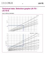
Technical data. Selection graphs LK-70 / LK-70-S Graph 4. VERTICAL DISCHARGE
Open the catalog to page 15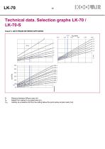
Technical data. Selection graphs LK-70 / LK-70-S Graph 5. AIR STREAM BETWEEN DIFFUSERS Distance between diffuser axes (m) Height from ceiling to occupied area (m) Velocity at a distance hR from the ceiling below the point where air jets meet (m/s)
Open the catalog to page 16
Technical data. Selection graphs LK-70 / LK-70-S Graph 6. AIR STREAM TOWARD THE WALL Horizontal distance from diffuser to wall + hR Velocity at the wall, at a distance hR from the ceiling
Open the catalog to page 17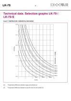
Technical data. Selection graphs LK-70 / LK-70-S Graph 7. TEMPERATURE, HORIZONTAL DISCHARGE Temperature difference between supply and ambient air. Temperature difference between air jet (for throw X) and ambient ai
Open the catalog to page 18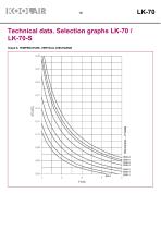
Technical data. Selection graphs LK-70 / LK-70-S Graph 8. TEMPERATURE, VERTICAL DISCHARGE
Open the catalog to page 19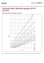
Technical data. Selection graphs LK-70 / LK-70-S Graph 9. INDUCTION RATE, HORIZONTAL DISCHARGE Induction rate. Quotient between the air volume moved by the air jet for a throw X and the supply air volume.
Open the catalog to page 20
Technical data. Selection graphs LK-70 / LK-70-S Graph 10. INDUCTION RATE, VERTICAL DISCHARGE
Open the catalog to page 21
Selection examples Example 1. Horizontal Air Supply The selection of an LK-70 linear diffuser is planned with the following design input: •Flow rate: 145 m3/h •Sound power < 35 dB(A) •Ceiling height: 3 m •Distance from the diffuser to the wall is 2.8 m •Distance between the diffusers (in the direction of the air supply): 5 m Starting with Graph 1 with a flow rate of 145 m3/h, we see that the sound power is 35 dB(A) for an LK 70 1500 – 1-slot linear diffuser, with a drop in pressure of 14 Pa. In order to obtain the effective velocity (Vk), we must first know the effective area of the diffuser...
Open the catalog to page 22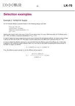
LK-70 Selection examples Example 2. Vertical Air Supply An LK-70 linear diffuser is selected based on the following design input data: •Flow rate: 330 m3/h •Sound power < 35 dB(A) •Maximum vertical penetration: 3 m •AT = +6 K Starting with Graph 4 with a flow rate of 330 m3/h we observe that, for a size 1000 three-slots LK-70 diffuser and a AT = +6 K, we obtain a maximum penetration of Ymax = 3 m. In order to obtain the sound output level and the drop in pressure for the selected diffuser, we need to look at Graph 2 with an air flow rate of 330 m3/h. We obtain a sound power level of 33 dB(A)...
Open the catalog to page 23
LK-70Product code The product code shown below is used to define both the diffuser as well as the plenum: Example: LK-70-1-1200-PFA-C RAL 9010 LK-70 linear diffuser, one-slot, and nominal width 1200 mm, 2 lengths of blades (standard), with insulated fixed plenum and integrated regulating damper in the spigot, coated in RAL-9010 white. LK-70-S Linear diffuser of narrow outer frame LK-70-MULTI Linear diffuser with slats of minimum length 100 mm LK-70-L Linear wall diffuser --- length of the diffuser (nominal, opening in mm) — no. of STANDARD lengths of deflector blades A no. of spans...
Open the catalog to page 24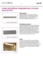
Linear slot diffuser integrated into a circular duct LK-70-C Description Supply linear slot diffuser, model LK-70-C, suitable for variable and constant volume. Integrated into a circular duct this diffuser frames has a 17-mm air passage, providing greater aesthetic appeal. The diffuser is suitable for large airflows at low velocities into the occupied zone. Recommended installation height between 2.5 and 4m. Finished products Standard finished products are made in galvanised sheet steel or painted in RAL-9010 gloss white equipped with adjustable blades manufactured in aluminium extrusion. The...
Open the catalog to page 25All KOOLAIR S.A catalogs and technical brochures
 series FLOOR
23 Pages
 series Dampers 100-2
21 Pages
 FIRE protection
2 Pages
 KOOLCOM
2 Pages
 DFRE-P
1 Page
 PE-45
PE-451 Page
 Acoustic
2 Pages
 Series 100-200 Dampers
18 Pages
 VENTILATION HOODS
6 Pages
 Series SF Fire dampers
35 Pages
 Series SCDC Smoke dampers
11 Pages
 36-STE
2 Pages
 DTP-GT Multi-nozzles diffusers
15 Pages
 DTP Multi-nozzles diffusers
14 Pages
 Koolair product range
2 Pages
 Technical Selection Guide
145 Pages
 Bypass terminal units – KMSR
15 Pages
 Terminal units with fan – HVFS
12 Pages
 Air Volume Boxes – Series KD
7 Pages
 Measurement Station – EM
6 Pages
 Passive chilled beams – VPK
9 Pages
 Induction terminal units – IHK
20 Pages
 Square diffusers – Series 50
22 Pages
 Multinozzles diffusers – DF49MT3
20 Pages
 Long-throw nozzles – DF 89
19 Pages
 Long-throw nozzles – DF 49
19 Pages
 Linear grilles – Series 30
19 Pages
 S26
S261 Page
 21-DVC/21-DVR
1 Page
 21-SVC/21-SVR
1 Page
 20-SH/21-SH
1 Page
 20-DH/21-DH
1 Page
 Circular diffusers – DCL
2 Pages
 Extract valves – Series GPD
8 Pages
 Circular diffusers – Series 40.1
31 Pages
 Security grilles – KSG
12 Pages
 Return grilles – Series 20.2
19 Pages
 Supply grilles – Series 26
10 Pages
 Regulating dampers
18 Pages
 Silencers – Series SK
25 Pages
 Linear Diffusers – Series 70.1
26 Pages
 Circular diffuser – Series 40.1
31 Pages
 Supply grilles – Series 20.1
19 Pages


- Ventilation grill
- Metal ventilation grill
- Rectangular ventilation grill
- Industrial air diffuser
- Square ventilation grill
- Ceiling-mounted air diffuser
- White ventilation grill
- Home ventilation grill
- Circular displacement air diffuser
- Square air diffuser
- Interior ventilation grill
- Ventilation damper
- Air filter
- Linear air diffuser
- Adjustable ventilation grill
- Metal ventilation damper
- Slot air diffuser
- Linear ventilation grill
- Stainless steel ventilation grill
- Industrial jet nozzle