- Catalogs
- KOOLAIR S.A
- series FLOOR
series FLOOR
1 /23Pages

series FLOOR
1 /23Pages
Catalog excerpts
DSA / DSA-PR / DSA-HV diffusers 4 DSA-HV Selection tables 10 DSA-HV Selection graphs 11 DSA-PR Selection tables 12 DSA-PR Selection graphs 13
Open the catalog to page 2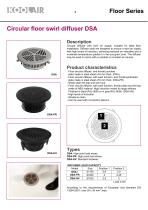
Description Circular diffuser with swirl air supply, suitable for false floor installation. Diffuser slots are designed to ensure a swirl air supply with high levels of induction, achieving reduced air velocities and a moderate temperature gradient in the occupied zone. The diffuser may be used in rooms with a variable or constant air volume. Product characteristics - Floor circular diffuser, and frontal punched plate made in steel sheet of 6 mm thick. (DSA) - Floor circular diffuser, with swirl function, and frontal perforated plate made in steel sheet of 6 mm thick. (DSA-PR) - Sheet steel dirt...
Open the catalog to page 3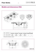
Floor SeriesModels and dimensions DSA Size - Dimensions for models DSA, DSA-PR
Open the catalog to page 4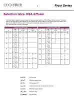
Technical data in regard to sound power and pressure drop refer to a DSA diffuser without plenum. Technical data for the DSA plenum box diffuser can be obtained by adding 4 dB(A) to the sound power level data in the table for the diffuser without a plenum box and increasing the pressure loss by 18%. The remaining data remains unchanged. Air flow rate Effective supply area Temperature AT Vertical throw for an air velocity of 0,25 m/s Effective supply velocity Pressure drop Sound power
Open the catalog to page 5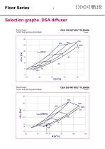
% (Dirt trap opening percentage) Graph 1 % (Dirt trap opening percentage) Graph 2
Open the catalog to page 6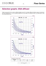
Floor Series Selection graphs. DSA diffuser Graphs showing the duct air velocity at different heights account for a possible difference between supply air temperature and room temperature of - 6 K; for a different differential, we must apply the coefficients shown in the table below, using the corresponding formula. Graph 3 Coefficient correction table -4 ∆T (K) 1,15 C
Open the catalog to page 7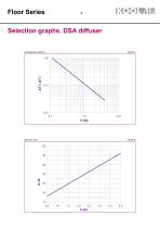
Floor Series Selection graphs. DSA diffuser Temperature quotient Induction rate
Open the catalog to page 8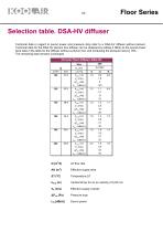
Floor SeriesSelection table. DSA-HV diffuser Technical data in regard to sound power and pressure drop refer to a DSA-HV diffuser without plenum. Technical data for the DSA-HV plenum box diffuser can be obtained by adding 4 dB(A) to the sound power level data in the table for the diffuser without a plenum box and increasing the pressure loss by 18%. The remaining data remains unchanged. Air flow rate Effective supply area Temperature AT Vertical throw for an air velocity of 0,25 m/s Effective supply velocity Pressure drop Sound power
Open the catalog to page 9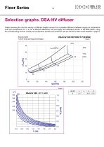
Floor SeriesSelection graphs. DSA-HV diffuser Graphs showing the duct air velocity at different heights account for a possible difference between supply air temperature and room temperature of - 6 K; for a different differential, we must apply the coefficients shown in the table below, using the corresponding formula. Graphs of Temperature quotient and induction rate are similar to DSA model detailed in page 9. Sound power DSA-HV 200 WITHOUT PLENUM % (Dirt trap opening percentage) Graph 7
Open the catalog to page 10
Floor SeriesSelection table. DSA-PR diffuser Technical data in regard to sound power and pressure drop refer to a DSA-PR diffuser without plenum. Technical data for the DSA-PR plenum box diffuser can be obtained by adding 4 dB(A) to the sound power level data in the table for the diffuser without a plenum box and increasing the pressure loss by 18%. The remaining data remains unchanged. Air flow rate Effective supply area Temperature AT Vertical throw for an air velocity of 0,25 m/s Effective supply velocity Pressure drop
Open the catalog to page 11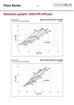
Floor SeriesSelection graphs. DSA-PR diffuserSound power DSA-PR 150 WITHOUT PLENUM % (Dirt trap opening percentage) Graph 9 Sound power DSA-PR 200 WITHOUT PLENUM % (Dirt trap opening percentage) Graph 10
Open the catalog to page 12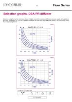
Floor SeriesSelection graphs. DSA-PR diffuser Graphs showing the duct air velocity at different heights account for a possible difference between supply air temperature and room temperature of - 6 K; for a different differential, we must apply the coefficients shown in the table below, using the corresponding formula.
Open the catalog to page 13
Floor Series Selection graphs. DSA-PR diffuser Temperature quotient Induction rate
Open the catalog to page 14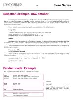
Floor SeriesSelection example. DSA diffuser In selecting the element for this type of diffusion, i.e. floor-level diffusion with temperature jumps no greater than ±6 °C, it is recommended not to exceed effective air velocity (VK) of 1.5 - 2 m/s to avoid generating irritating air currents in the occupied area (>0,25 m/s). This is particularly relevant when using this type of diffuser under seats in locations such as auditoriums. Shown below is an example giving a graph-based explanation of the selection method. Design data Auditorium with 410 seats. Total air supply volume in seating area: 22500...
Open the catalog to page 15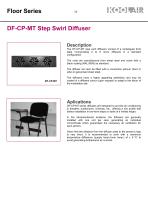
Floor Series DF-CP-MT Step Swirl Diffuser Description The DF-CP-MT step swirl diffusers consist of a rectangular front plate incorporating 2 to 6 micro diffusers in a standard configuration. The units are manufactured from sheet steel and come with a black coating (RAL 9005) as standard. The diffuser can also be fitted with a connection plenum (front or side) in galvanised sheet steel. The diffusers have a highly appealing aesthetics and may be coated in a different colour (upon request) to adapt to the décor of the installation site. Aplications DF-CP-MT series diffusers are designed to provide...
Open the catalog to page 16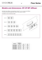
Floor SeriesModels and dimensions. DF-CP-MT diffuser DF-CP-MT series diffusers can manufactured in sets of 2, 3, 4, 5, or 6 swirl micro-diffusers. The diffusers can also be supplied with a plenum at the customer’s request. The diffusers come in the following models:
Open the catalog to page 17
Floor Series Models and dimensions. DF-CP-MT diffuser TOP ENTRY PLENUM SIDE ENTRY PLENUM
Open the catalog to page 18
Floor Series Technical data. DF-CP-MT diffuser SOUNDS LEVEL SELECTION TABLE: The air flow rate and pressure drop (values in parenthesis) for each diffuser size are determined according to the desired sound level. The graph below shows the air velocity (of a micro-diffuser) measured at 100 mm from the floor according to the height of the unit. Depending on the number of elements that make up the plate, the velocity value shown in the graph is multiplied by that shown in table 2. Table 2: Correction values for 2 to 6 micro-diffusers
Open the catalog to page 19All KOOLAIR S.A catalogs and technical brochures
 series Dampers 100-2
21 Pages
 FIRE protection
2 Pages
 KOOLCOM
2 Pages
 DFRE-P
1 Page
 PE-45
PE-451 Page
 Acoustic
2 Pages
 Series 100-200 Dampers
18 Pages
 VENTILATION HOODS
6 Pages
 Series SF Fire dampers
35 Pages
 Series SCDC Smoke dampers
11 Pages
 36-STE
2 Pages
 DTP-GT Multi-nozzles diffusers
15 Pages
 DTP Multi-nozzles diffusers
14 Pages
 Koolair product range
2 Pages
 Technical Selection Guide
145 Pages
 Bypass terminal units – KMSR
15 Pages
 Terminal units with fan – HVFS
12 Pages
 Air Volume Boxes – Series KD
7 Pages
 Measurement Station – EM
6 Pages
 Passive chilled beams – VPK
9 Pages
 Induction terminal units – IHK
20 Pages
 Square diffusers – Series 50
22 Pages
 Multinozzles diffusers – DF49MT3
20 Pages
 Long-throw nozzles – DF 89
19 Pages
 Long-throw nozzles – DF 49
19 Pages
 Linear grilles – Series 30
19 Pages
 S26
S261 Page
 21-DVC/21-DVR
1 Page
 21-SVC/21-SVR
1 Page
 20-SH/21-SH
1 Page
 20-DH/21-DH
1 Page
 Circular diffusers – DCL
2 Pages
 Extract valves – Series GPD
8 Pages
 Circular diffusers – Series 40.1
31 Pages
 Security grilles – KSG
12 Pages
 Return grilles – Series 20.2
19 Pages
 Supply grilles – Series 26
10 Pages
 Regulating dampers
18 Pages
 Silencers – Series SK
25 Pages
 Linear Diffusers – Series 70.1
26 Pages
 Circular diffuser – Series 40.1
31 Pages
 Supply grilles – Series 20.1
19 Pages


- Ventilation grill
- Metal ventilation grill
- Rectangular ventilation grill
- Industrial air diffuser
- Square ventilation grill
- Ceiling-mounted air diffuser
- White ventilation grill
- Home ventilation grill
- Circular displacement air diffuser
- Square air diffuser
- Interior ventilation grill
- Ventilation damper
- Air filter
- Linear air diffuser
- Adjustable ventilation grill
- Metal ventilation damper
- Slot air diffuser
- Linear ventilation grill
- Stainless steel ventilation grill
- Industrial jet nozzle