Catalog excerpts

Table of Contents Page 100 Series Regulating Dampers __________________________________________________ 4 Overview ______________________________________________________________________ 5 Graphs ________________________________________________________________________ 6 200 Series Outside Air Intake Louvers _____________________________________________ 8 Overview ______________________________________________________________________ 9 Selection Table and Dimensions ____________________________________________________ 10 Load Loss Graphs...
Open the catalog to page 2
100 Series Regulating Dampers Description Regulating damper with opposed and aerodynamic vanes, manufactured in aluminium (AOBD-102-E). The body of the damper has built-in air tight gaskets all around its inner perimeter to ensure a tight seal. The movement of the vanes is ensured by means of gears, achieving a proper friction, with manual or motor-driven operation. Vanes are available with 75 and 100 mm vane axis distances, to complete the entire range of standard duct dimensions Manually Operated Model AOBD-102-E Flat parallel-vane (SOBD-105) or opposite-vane (SOBD106) regulating dampers,...
Open the catalog to page 3
The dimensions indicated below are standard for regulating dampers. Regarding the length and height, they can be manufactured using intermediate dimensions, with 50mm vane axis distances. Regulating damper model AOBD-102-E Regulating damper model SPBD-105 and SOBD-106 L
Open the catalog to page 4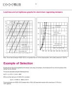
Load loss and air tightness graphs for aluminium regulating dampers Completely closed Manual operation Completely closed Turn moment 60 Kg x cm. Motor-driven LOAD LOSS TYPE AOBD-102-E Opposed aerodynamic vanes Opposed aerodynamic vanes Leaks % of maximum flow Note: The air leak at damper AOBD-102-E is not greater than 2% in the closed position, with a static pressure of 1250 Pa. Example of Selection Knowing the air flow to be regulated by the damper, and using, for example, a front velocity of 6 m/s, the front surface of the damper can be obtained. This can be calculated using the following...
Open the catalog to page 5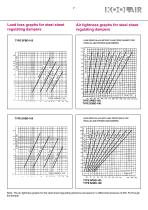
Load loss graphs for steel sheet regulating dampers TYPE SPBD-105 Air tightness graphs for steel sheet regulating dampers LEAK GRAPH IN m3/h WITHOUT LEAK PROOF GASKETS FOR PARALLEL AND OPPOSED VANE DAMPERS Flow m3/h Front velocity: m/s. LEAK GRAPH IN m3/h WITH LEAK PROOF SEALS FOR PARALLEL AND OPPOSED VANE DAMPERS Note: The air-tightness graphs for the steel sheet regulating dampers are based on a differential pressure of 250 Pa through the damper.
Open the catalog to page 6
Weather louvres serie 200 Description Weather louvre for intake or discharge, model 210 TA In natural aluminium (without anodising). Special finishes available upon request. 210 TA Weather louvre for intake or discharge, constructed in extruded aluminium. Its design and blade shape avoid vision through the louvre. It avoids penetration of rain water, snow, etc., since it has been principally designed for outdoor installation. It can be provided with bird screen or insect screen. Fixing The louvres incorporate fasteners in the frame for installation. Upon request the frame can be delivered...
Open the catalog to page 7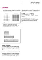
- As an accessory the weather louvres 210TA incorporate a birdscreen or an insect screen. Free area: (L-14)*(H-109) mm = [(1000-14)* (650-109)]/ 106= 0,53 m2 Face velocity (Vf) = 5000/0,53/3600= 2,6 m/s Pressure loss at intake for louvre with birdscreen: 30Pa. Pressure loss at discharge for louvre with birdscreen: 35Pa. - Can be built as a single module upto maximum dimensions of 3000 x 2000 mm (width x height). For widths above 1000 mm central reinforcements are incorporated as shown below. Example of selection For a known air flow rate which should pass through the louvre at, for example,...
Open the catalog to page 8
500 600 700 750 800 900 1000 1100 1200 1300 1400 1500 2000 2250 2500 2750 3000 Note : Dimensions in width (L) may be varied upon request. The louvres can be provided in intermediate height dimensions as multiples of 50 mm (e.g. 250, 350, 450 mm, etc...)
Open the catalog to page 9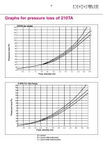
Graphs for pressure loss of 210TA Face velocity m/s A.- Louvre B.- Louvre with birdscreen C.- Louvre with insect screen
Open the catalog to page 10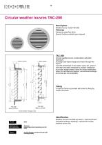
Circular weather louvres TAC-200 Description Weather louvre, model TAC-200 Finishes Painted in white RAL 9010. Special finishes available upon request. Bird screen Circular weather louvre, constructed in extruded aluminium. Its design and blade shape avoid vision through the louvre. It avoids penetration of rain water, snow, etc., since it has been principally designed for outdoor installation. Its circular shape makes it ideal for those installations where, for architectural reasons, conventional rectangular louvres are not acceptable. Fixing The louvre frame is provided with holes for...
Open the catalog to page 11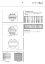
General dimensions In the following general dimensions for the TAC-200 louvres are given in two tables : from Ø315 to Ø710 with insectscreen and from Ø800 to Ø1250 with birdscreen. B 40 40 40 40 40 40 Accessories In standard finish the TAC louvres incorporate an insectscreen from size 315 to 710 and a birdscreen from 800 to 1250.
Open the catalog to page 12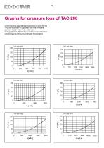
Graphs for pressure loss of TAC-200 In the following graphs the pressure loss is given for the TAC-200 louvres. For a given air flow rate (m3/h) the pressure loss (in Pa) can be obtained. In all graphs the effect of the insectscreen or birdscreen (according to louvre size) are already incorporated.
Open the catalog to page 13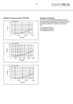
Graphs for pressure loss of TAC-200 TAC-200 Ø800 Example of selection For a known air flow rate passing through the louvre, the size should be selected such that the pressure loss corresponds to the requirements. For example, for an air flow rate of 3000 m3/h a selection can be made from: TAC-200 Ø630 with 85 Pa TAC-200 Ø710 with 55 Pa TAC-200 Ø800 with 14 Pa
Open the catalog to page 14
Overpressure dampers serie 200, type 230 SP Description Overpressure damper model 230 SP Finishes Natural aluminium (without anodising) Special finishes are available upon request General dimensions See page 18. Other dimensions according to the drawings on the left. 230 SP Overpressure damper constructed in extruded aluminium. Incorporates a strip on the blades to obtain a higher shutter efficiency and noise reduction. Can be provided upon request with frame in “u” shape, inverted blades, interconnected blades, etc... Fixing Dampers 230 SP incorporate holes in the frame for wall or duct...
Open the catalog to page 15All KOOLAIR S.A catalogs and technical brochures
-
series FLOOR
23 Pages
-
series Dampers 100-2
21 Pages
-
FIRE protection
2 Pages
-
KOOLCOM
2 Pages
-
DFRE-P
1 Pages
-
PE-45
1 Pages
-
Acoustic
2 Pages
-
VENTILATION HOODS
6 Pages
-
Series SF Fire dampers
35 Pages
-
Series SCDC Smoke dampers
11 Pages
-
36-STE
2 Pages
-
DTP-GT Multi-nozzles diffusers
15 Pages
-
DTP Multi-nozzles diffusers
14 Pages
-
Koolair product range
2 Pages
-
Technical Selection Guide
145 Pages
-
Bypass terminal units – KMSR
15 Pages
-
Terminal units with fan – HVFS
12 Pages
-
Air Volume Boxes – Series KD
7 Pages
-
Measurement Station – EM
6 Pages
-
Passive chilled beams – VPK
9 Pages
-
Induction terminal units – IHK
20 Pages
-
Square diffusers – Series 50
22 Pages
-
Multinozzles diffusers – DF49MT3
20 Pages
-
Long-throw nozzles – DF 89
19 Pages
-
Long-throw nozzles – DF 49
19 Pages
-
Linear grilles – Series 30
19 Pages
-
S26
1 Pages
-
21-DVC/21-DVR
1 Pages
-
21-SVC/21-SVR
1 Pages
-
20-SH/21-SH
1 Pages
-
20-DH/21-DH
1 Pages
-
Circular diffusers – DCL
2 Pages
-
Extract valves – Series GPD
8 Pages
-
Circular diffusers – Series 40.1
31 Pages
-
Security grilles – KSG
12 Pages
-
Return grilles – Series 20.2
19 Pages
-
Supply grilles – Series 26
10 Pages
-
Regulating dampers
18 Pages
-
Silencers – Series SK
25 Pages
-
Linear Diffusers – Series 70.1
26 Pages
-
Circular diffuser – Series 40.1
31 Pages
-
Supply grilles – Series 20.1
19 Pages


