- Catalogs
- KOOLAIR S.A
- Motor-driven fire damper monitoring systems – KOOLCOM
Motor-driven fire damper monitoring systems – KOOLCOM
1 /22Pages

Motor-driven fire damper monitoring systems – KOOLCOM
1 /22Pages
Catalog excerpts

KOOLCOM Motor-driven fire damper monitoring systems
Open the catalog to page 1
General system schematic diagram 3 KHUK connection schematic diagram 14
Open the catalog to page 2
KOOLCOM fire damper monitoring system. Introduction KOOLCOM is an electronic control system for fire dampers that allows the condition and functionality of each fire damper to be periodically and automatically monitored and checked. It can also close the dampers should the fire alarm be activated. While this system is capable of being managed by a BMS (Building Management System) system, KOOLCOM can also work in Standalone mode, i.e., operate autonomously without the need for a BMS or any external maintenance personnel. Graphic console KOOLCOM is the only system on the market whose installation...
Open the catalog to page 3
Note: If the KHUK alarm input is connected to a fire panel, the modbus wiring between KHUK and DCUs, and between KHUK and the BMS, must be flame retardant. (Possible connections for 1 to 247 KHUKs). (Possible connections for 1 to 32 DCUs). (Possible connections for 1 to 32 DCUs). A - Power Connection-KHUK. 24V. 2 Wires. Observe polarity +24V and GND(-). B - KHUK-RESET PUSH BUTTON. 24V.2 Wires. Observe polarity RESET and +24V C - KHUK- INPUT FROM ALARM PANEL. 2 Wires. Observe polarity. +24V and ALARM. D - KHUK-KHUK. ModBus. 3 Wires. Observe polarity A+, B- and GND. E - KHUK-DCU. ModBus. 3 Wires....
Open the catalog to page 4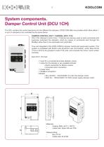
System components. Damper Control Unit (DCU 1CH) The DCU contains the control electronics for the different fire dampers. KOOLCOM offers two models which allow either 1, or up to 4 dampers to be controlled by the same device. DAMPER CONTROL UNIT 1 CHANNEL (DCU 1CH) DCU 1CH (Damper Control Unit, 1 Channel) are devices used to send commands and supervise motorised fire dampers, which by means of commands sent through the ModBus allow them to be automated and controlled. They are integrated in the KOOLCOM fire damper control and supervision system. This system is completed with KHUK units (KoolCom...
Open the catalog to page 5
• Maximum load on the damper motor output: 24V (AC/DC) model: 3A • Maximum load in the detection zone: 100mA • Maximum power consumption (without detector or damper): 24V (AC/DC) model: 100mA@24V • Protected against short circuits and ESDs at zone connections, fire damper contacts, and ModBus. • MODBUS: - Device type: Slave - ModBus implementation: RTU on RS-485 - Maximum number of DCUs (without repeater): 32 - Default configuration: 9600bps 8E1 - Bus data transfer speed can be configured both on the PCB and via ModBus. - Integrated termination in PCB, can be activated by jumper. • Installer...
Open the catalog to page 6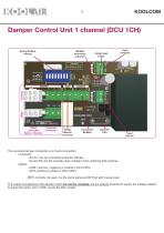
Binary ModBus address ModBus termination activation Default load values Ij A DAMPER OUTPUTS ' /'\ ARE rTTSTi DRY CONTACTS Direct connection Belimo / Siemens Universal connection Smoke detector connector Connection ModBus The universal damper connection is a 5-wire connection: o Contacts: - S4+S1: can be connected inside the damper. - S2 and S6: Are the normally open contacts of the matching limit switches. o Motor: - COM: common, negative (or neutral in DCU 230V) - MOT: positive (or phase in DCU 230V) MOT: normally not used, it is the same signal as MOT but with inverse logic. The output connections...
Open the catalog to page 7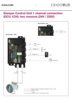
Damper Control Unit 1 channel connection (DCU 1CH): two versions (24V / 230V) 100-DCK300 - 24V: Power supply 230V (cable tie is essential) or 24V. 2 wires. ModBus. 3 wires. DAMPER 2 Wires. Contacts 3 wires + motor supply 2 wires.
Open the catalog to page 8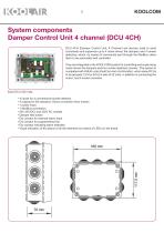
DCU 4CH (Damper Control Unit, 4 Channel) are devices used to send commands and supervise up to 4 motor-driven fire dampers and 4 smoke detectors, which, by means of commands sent through the ModBus, allow them to be automated and controlled They are integrated in the KOOLCOM system for controlling and supervising motor-driven fire dampers and four smoke detectors (zones). This system is completed with KHUK units (KoolCom Hub Unit KoolAir), which allow DCUs to be grouped (1CH or 4CH) in sets of 32 units, in addition to connecting the colour, touch screen consoles. • 4 inputs for a conventional...
Open the catalog to page 9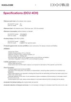
• Maximum joint load on the damper motor outputs: 24V (AC/DC) model: 3A • Maximum load in the detection zone: 100mA per zone / 300 mA combined • Maximum consumption (without detector or damper): 24V (AC/DC) model: 100mA@24V • Auxiliary Relays (FAN AND ALARM): 24V (AC/DC) model: 5 A@24V 230V AC model: 5 A@230V (for resistive loads) • Protected against short circuits and ESDs at zone connections, fire damper contacts and ModBus. • MODBUS: - Device type: Slave - ModBus implementation: RTU on RS-485 - Maximum number of DCUs (without repeater): 32 - Default configuration: 9600bps 8E1 -...
Open the catalog to page 10
KOOLCOM Damper Control Unit 4 channel (DCU 4CH) V. INPUT POWER 230V ALR DAMPER DRY CONTACT OUTPUT activated in the event of an alarm FAN DAMPER DRY CONTACT OUTPUT supply, can be configured for extract MODBUS ADDRESS CONFIGURATION INSTALLER PUSH BUTTON SMOKE SMOKE SMOKE SMOKE DETECTOR 1 DETECTOR 2 DETECTOR 3 DETECTOR 4 The universal damper connection uses 4 wires: o Contacts: - S2 and S6: are the normally open contacts of the matching limit switches. o Motor: - COM + S4 + S1: common, negative (or neutral in DCU 230V) attached to cables S4 and S1 of the motor contacts. - MOTx: positive (or phase...
Open the catalog to page 11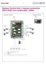
Damper Control Unit 1 channel connection (DCU 4CH): two models (24V / 230V) 100-DCK100 - 24V AC/DC: 100-DCK200 - 230V AC: Power 24V 2 1 Alarm input Exterior ModBus : IN ' ----- 230V AC or 24V AC/DC supply. 2 wires. — — — ModBus. 3 wires. ----2 wires. --------2 wires. -2 wires contacts (S2, S6) + 2 wires motor supply (COM+S4+S1), MOTx.
Open the catalog to page 12
System components. KHUK (HUB) The KHUK is a Modbus hub device that occupies a single address, allows up to 128 fire dampers and 128 smoke detectors (32 DCU-4CH units) to be managed. Each KHUK has: - 1 connection to the Koolcom console. - Direct connection to fire panel: • Alarm activation input. • Alarm reset input. • NO alarm relay output (Max 8Amp). - 1 24V DC power input. - Maximum consumption: 100–UCK000: 125mA@24v - 1 ModBus connection on RS485 for DCUs. - 1 ModBus connection on RS485 for BMS. - ModBus: Type of device going to DCUs: Type of device going to the BMS: ModBus implementation:...
Open the catalog to page 13All KOOLAIR S.A catalogs and technical brochures
 series FLOOR
23 Pages
 series Dampers 100-2
21 Pages
 FIRE protection
2 Pages
 KOOLCOM
2 Pages
 DFRE-P
1 Page
 PE-45
PE-451 Page
 Acoustic
2 Pages
 Series 100-200 Dampers
18 Pages
 VENTILATION HOODS
6 Pages
 Series SF Fire dampers
35 Pages
 Series SCDC Smoke dampers
11 Pages
 36-STE
2 Pages
 DTP-GT Multi-nozzles diffusers
15 Pages
 DTP Multi-nozzles diffusers
14 Pages
 Koolair product range
2 Pages
 Technical Selection Guide
145 Pages
 Bypass terminal units – KMSR
15 Pages
 Terminal units with fan – HVFS
12 Pages
 Air Volume Boxes – Series KD
7 Pages
 Measurement Station – EM
6 Pages
 Passive chilled beams – VPK
9 Pages
 Induction terminal units – IHK
20 Pages
 Square diffusers – Series 50
22 Pages
 Multinozzles diffusers – DF49MT3
20 Pages
 Long-throw nozzles – DF 89
19 Pages
 Long-throw nozzles – DF 49
19 Pages
 Linear grilles – Series 30
19 Pages
 S26
S261 Page
 21-DVC/21-DVR
1 Page
 21-SVC/21-SVR
1 Page
 20-SH/21-SH
1 Page
 20-DH/21-DH
1 Page
 Circular diffusers – DCL
2 Pages
 Extract valves – Series GPD
8 Pages
 Circular diffusers – Series 40.1
31 Pages
 Security grilles – KSG
12 Pages
 Return grilles – Series 20.2
19 Pages
 Supply grilles – Series 26
10 Pages
 Regulating dampers
18 Pages
 Silencers – Series SK
25 Pages
 Linear Diffusers – Series 70.1
26 Pages
 Circular diffuser – Series 40.1
31 Pages
 Supply grilles – Series 20.1
19 Pages


- Ventilation grill
- Metal ventilation grill
- Rectangular ventilation grill
- Industrial air diffuser
- Square ventilation grill
- Ceiling-mounted air diffuser
- White ventilation grill
- Home ventilation grill
- Circular displacement air diffuser
- Square air diffuser
- Interior ventilation grill
- Ventilation damper
- Air filter
- Linear air diffuser
- Adjustable ventilation grill
- Metal ventilation damper
- Slot air diffuser
- Linear ventilation grill
- Stainless steel ventilation grill
- Industrial jet nozzle