
Catalog excerpts

Selection and correction charts 5
Open the catalog to page 2
DF-49 long-throw nozzle Description The DF-49 combines long-throw efficiency with a more harmonious design. The stylised lines of the nozzles and the possibility of matching current decorative styles make these diffusers a reliable, great-looking component for facilities with more stringent requirements in terms of design and comfort. Interior architecture are increasingly designing larger spaces for hotels, shopping malls, salons, convention centres, airport vestibules, passenger stations, social halls, etc. MM Con MM Para MM In addition to effective air blowing at a long distance through...
Open the catalog to page 3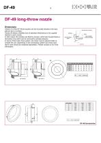
Dimensions Version A of the DF-49 jet nozzles can be mounted directly to the duct, plenum box or surface. Version B allows a flexible duct of standard dimensions to be coupled directly to each nozzle. In both cases, the nozzles are fixed by screws, which are housed below a decorative ring which can be removed by simple pressure. In terms of the motor drive system, the motor may be placed inside or outside the unit, depending on the connection system and motor type (each case should be analysed separately). Please contact us for more information.
Open the catalog to page 4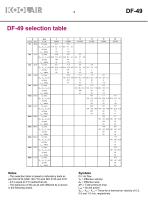
Notes - This selection table is based on laboratory tests as per ISO 5219 (UNE 100.710) and ISO 5135 and 3741. - AT is equal to 0°C (isothermal air). - The behaviour of the air jet with different At is shown in the following charts. Symbols Q = Air flow VK = Effective velocity AK = Effective area APt = Total pressure drop LwA = Sound power X0,3 - X0,5 - Xi,0 = Throw for a terminal air velocity of 0.3, 0.5 and 1.0 m/s, respectively.
Open the catalog to page 5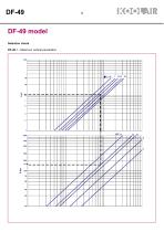
DF-49 DF-49 model Selection charts DF-49-1.- Maximum vertical penetration.
Open the catalog to page 6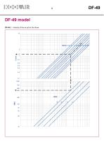
DF-49 model DF-49-2.- Velocity of the air jet for the throw.
Open the catalog to page 7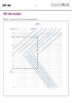
DF-49 model DF-49-3.1.- Vertical deviation of the air jet (non-isothermal jets).
Open the catalog to page 8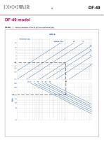
DF-49 model DF-49-3. 2.- Vertical deviation of the air jet (non-isothermal jets).
Open the catalog to page 9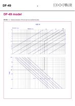
DF-49 model DF-49-3. 3.- Vertical deviation of the air jet (non-isothermal jets).
Open the catalog to page 10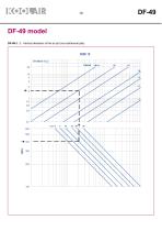
DF-49 model DF-49-3. 3.- Vertical deviation of the air jet (non-isothermal jets).
Open the catalog to page 11
DF-49 model DF-49-3. 4.- Vertical deviation of the air jet (non-isothermal jets).
Open the catalog to page 12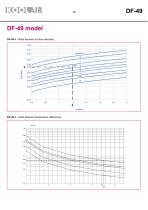
DF-49 model DF-49-4.- Ratio between air flow velocities. DF-49-5.- Ratio between temperature differences.
Open the catalog to page 13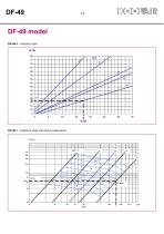
DF-49 DF-49 model DF-49-6.- Induction rate. DF-49-7.- Pressure drop and sound power level.
Open the catalog to page 14
DF-49 Selection in a sample project Initial data Two DF-49 nozzles are located, one in front of the other at a distance of 24 m, with the following starting data based on the sketch attached in the Symbols section on page 16. - L = 12 m - H = 4 m (height from floor) - Qnozzle = 400 l/s - Supply temperature = 15° C - Room temperature = 25° C - AT0 = -10° C - Hh = 2 m (height of occupied area) The diffuser should be selected to obtain the following: - Maximum velocity in the occupied area: 0,2 m/s. - The vertical temperature gradient must not exceed 3 °C. - The sound power level of the...
Open the catalog to page 15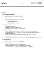
DF-49 Selection - DF-49 quick selection table (page 4) Based on the sound power limit, size 16 is preselected. - DF-49-7 chart (page 13) Using size 16 for 400 l/s, the following values are obtained: - APt= 54 Pa (pressure drop) - LwA= 34 dB(A) (sound power level) - DF-49-2 chart (page 6) For a supply angle of aX= +15° C, The throw will be I=L/cos 15°=12/0,966=12,42 m According to the chart, the velocity for this throw is VX=1,2 m/s - DF-49-3.4 chart (page 11) The impact point under isothermal conditions would be H+HC=H+(L x tan 15°)=4+(12x0,268)=7,2 m The chart indicates that for AT0 = -10°...
Open the catalog to page 16
DF-49 Symbols Common symbols used in all tables and charts in the catalogue. Distance between the equipment to the impact point of the jets (with another jet or wall) under isothermal conditions. Supply angle. Horizontal distance from the equipment to the impact point of the jets (with another jet or wall). Throw of the air jet. Deviation of the air jet caused by a temperature difference between the supply and ambient air. Installation height of the equipment. Height of occupied area. Height from the impact point of the jets (with another jet or wall) under isothermal conditions with...
Open the catalog to page 17
THIS CATALOGUE IS INTELLECTUAL PROPERTY. Reproduction, either partial or total, by any means, including electronic, is prohibited without prior written authorisation from KOOLAIR, S.A. . CEN-DF-49-0815-00
Open the catalog to page 18
KOOLAIR, S.A. Calle Urano, 26 Poligono industrial nº 2 – La Fuensanta 28936 Móstoles - Madrid - (España) Tel: +34 91 645 00 33 Fax: +34 91 645 69 62 e-mail: info@koolair.com
Open the catalog to page 19All KOOLAIR S.A catalogs and technical brochures
-
series FLOOR
23 Pages
-
series Dampers 100-2
21 Pages
-
FIRE protection
2 Pages
-
KOOLCOM
2 Pages
-
DFRE-P
1 Pages
-
PE-45
1 Pages
-
Acoustic
2 Pages
-
Series 100-200 Dampers
18 Pages
-
VENTILATION HOODS
6 Pages
-
Series SF Fire dampers
35 Pages
-
Series SCDC Smoke dampers
11 Pages
-
36-STE
2 Pages
-
DTP-GT Multi-nozzles diffusers
15 Pages
-
DTP Multi-nozzles diffusers
14 Pages
-
Koolair product range
2 Pages
-
Technical Selection Guide
145 Pages
-
Bypass terminal units – KMSR
15 Pages
-
Terminal units with fan – HVFS
12 Pages
-
Air Volume Boxes – Series KD
7 Pages
-
Measurement Station – EM
6 Pages
-
Passive chilled beams – VPK
9 Pages
-
Induction terminal units – IHK
20 Pages
-
Square diffusers – Series 50
22 Pages
-
Multinozzles diffusers – DF49MT3
20 Pages
-
Long-throw nozzles – DF 89
19 Pages
-
Linear grilles – Series 30
19 Pages
-
S26
1 Pages
-
21-DVC/21-DVR
1 Pages
-
21-SVC/21-SVR
1 Pages
-
20-SH/21-SH
1 Pages
-
20-DH/21-DH
1 Pages
-
Circular diffusers – DCL
2 Pages
-
Extract valves – Series GPD
8 Pages
-
Circular diffusers – Series 40.1
31 Pages
-
Security grilles – KSG
12 Pages
-
Return grilles – Series 20.2
19 Pages
-
Supply grilles – Series 26
10 Pages
-
Regulating dampers
18 Pages
-
Silencers – Series SK
25 Pages
-
Linear Diffusers – Series 70.1
26 Pages
-
Circular diffuser – Series 40.1
31 Pages
-
Supply grilles – Series 20.1
19 Pages


