- Catalogs
- KOOLAIR S.A
- Induction terminal units – IHK
Induction terminal units – IHK
1 /20Pages

Induction terminal units – IHK
1 /20Pages
Catalog excerpts
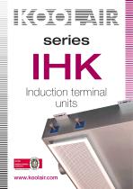
Induction terminal units
Open the catalog to page 1
Induction terminal units CONTENTS Page Induction terminal unit IHK-F 5 Induction terminal unit IHK-V 6
Open the catalog to page 2
General Features Description The IHK ceiling-mounted induction terminal units are used in air-water systems to provide a high level of comfort in interior environments with high internal thermal loads in cooling operation. The IHK units are recommended for bulkhead and suspended ceiling installation. Ideal for hotel guest rooms and hospitals. The units include the following components: .Primary air plenum, with one round duct connections for priIHK mary air inlet and a distribution of small nozzles with alternative settings. Hot or chilled water (two-pipe installation) or hot and chilled water...
Open the catalog to page 3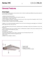
General Features Advantages The IHK ceiling-mounted induction units are terminal units for central air conditioning installations that provide solutions to meet the needs of the following: .Ventilation achieved with primary air .Cooling, based on the primary air itself and the water circulation coil .Heating, based on a water circulation coil .Control. Possibility of individual or combined unit control by room or area, using control and regulation valves in the unit to adjust the water volume and room thermostats .Air diffusion based on a grille that ensure effective air diffusion. In addition...
Open the catalog to page 4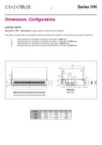
Series IHK Dimensions. Configurations LATERAL ENTRY Sizes 900 to 1500 - 4-pipe system (2-pipe system connections also available) Four types of configurations are available, defined according to the position of the primary air and water connections: 1. Lateral primary air connection and water on left side, (-LIWI) type 2. Lateral primary air connection on left side and water on rigth side, (-LIWD) type 3. Lateral primary air connection and water on rigth side, (-LDWD) type 4. Lateral primary air connection on rigth side and water on left side, (-LDWI)...
Open the catalog to page 5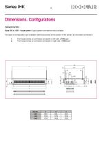
Series IHK Dimensions. Configurations FRONT ENTRY Sizes 900 to 1500 - 4-pipe system (2-pipe system connections also available) Two types of configurations are available, defined according to the position of the primary air and water connections: 1. Front face primary air connection and water on left side, (-FWI) type 2. Front face primary air connection and water on rigth side, (-FWD) type
Open the catalog to page 6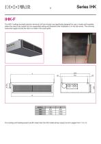
Series IHK IHK-F The IHK-F ceiling-mounted induction terminal unit from Koolair are specifically designed for use in hotels and hospitals, where the area to be cooled has not suspended ceiling and therefore their installation is in the hall annex. The one-way horizontal supply air and the return is made in the same grille. The cooling and heating powert are 8% lower than the IHK model whose values found in pages from 11 to 14.
Open the catalog to page 7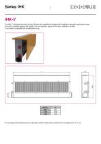
Series IHK IHK-V The IHK-V induction terminal unit from Koolair are specifically designed for installation along the perimeter zones. The unit is installed against the facade, it is not required space on the floor, ceiling or corridor. This model is available with condensation tray. The cooling and heating powert are equals the IHK model whose values found in pages from 11 to 14.
Open the catalog to page 8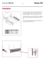
Series IHK Installation The IHK units include a series of hanging brackets on the two upper longitudinal sides of the units, as shown in the following photographs. There are two brackets per side. These brackets have a slot hole to hold a 06 mm threaded rod, which is first attached to the ceiling slab to hang the unit. The unit can be fixed directly to the ceiling surface or suspended using threaded drop rods.
Open the catalog to page 9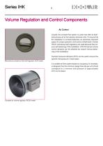
Volume Regulation and Control Components - Air Usually, the constant flow system is used most often to distribute primary air to the induction terminal units. To ensure that the installation is correctly balanced, an extremely important aspect for proper operation of the active chilled beam, Koolair RCCK mechanical self-regulators are used because they ensure self-balancing of the installation. CRC-M manual volume control dampers can be selected but require manual balancing of the installation. Ductwork pressure dampers (RVV) can be used to ensure the specific inlet pressure in each beam. Mechanical...
Open the catalog to page 10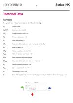
Series IHK Technical Data Symbols The symbols used in the selection tables for the IHK are the following: Qpr Primary air flow Lw-dB(A) Sound power level, in dB(A) DPpr Primary air pressure drop, in Pa DTpr Temperature difference between room air and primary air (TR - Tpr) QW Water flow rate, in L/h APw Water pressure drop in the coil, in kPa TW|N Water inlet temperature in the coil, in oC ATw Water temperature difference in the coil ATswin Temperature difference between room and unit water inlet Ppr Capacity supplied by primary air, in W P SW Capacity supplied...
Open the catalog to page 11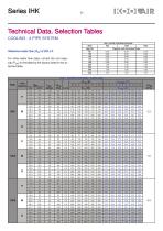
Series IHKTechnical Data. Selection Tables COOLING - 2-PIPE SYSTEM
Open the catalog to page 12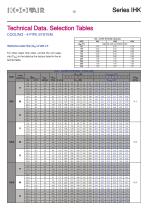
Series IHK Technical Data. Selection Tables COOLING - 4-PIPE SYSTEM
Open the catalog to page 13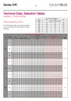
Series IHKTechnical Data. Selection Tables HEATING - 2 -PIPE SYSTEM
Open the catalog to page 14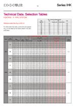
Series IHK Technical Data. Selection Tables HEATING - 4 -PIPE SYSTEM
Open the catalog to page 15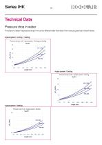
Technical Data Pressure drop in water The charts to obtain the pressure drop in the coil for different water flow rates in the various systems are shown below: 2-pipe system. Cooling - Heating Pressure drop in coil - 2 pipes system - Cooling and Heating 4-pipe system. Cooling Pressure drop in coil - 4 pipes system - Cooling Pressure drop in coil - 4 pipes system - Heating
Open the catalog to page 16
Product Codes Coding example of an order. All of the different models, sizes, accessories, etc., existing in the KOOLAIR IHK series are listed. (a): Model IHK standard induction terminal unit IHK-F induction terminal unit, supply and return in the same grille IHK-V perimetral induction terminal unit (b): Length IHK : 900 - 1200 - 1500 (mm) (d): Coil Type of system. - 2 2-pipe system coil - 4 4-pipe system coil (e): Air/water connection configuration - FWI Front face primary air connection and water connection on left - FWD Front face primary air connection and water connection on...
Open the catalog to page 17All KOOLAIR S.A catalogs and technical brochures
 series FLOOR
23 Pages
 series Dampers 100-2
21 Pages
 FIRE protection
2 Pages
 KOOLCOM
2 Pages
 DFRE-P
1 Page
 PE-45
PE-451 Page
 Acoustic
2 Pages
 Series 100-200 Dampers
18 Pages
 VENTILATION HOODS
6 Pages
 Series SF Fire dampers
35 Pages
 Series SCDC Smoke dampers
11 Pages
 36-STE
2 Pages
 DTP-GT Multi-nozzles diffusers
15 Pages
 DTP Multi-nozzles diffusers
14 Pages
 Koolair product range
2 Pages
 Technical Selection Guide
145 Pages
 Bypass terminal units – KMSR
15 Pages
 Terminal units with fan – HVFS
12 Pages
 Air Volume Boxes – Series KD
7 Pages
 Measurement Station – EM
6 Pages
 Passive chilled beams – VPK
9 Pages
 Square diffusers – Series 50
22 Pages
 Multinozzles diffusers – DF49MT3
20 Pages
 Long-throw nozzles – DF 89
19 Pages
 Long-throw nozzles – DF 49
19 Pages
 Linear grilles – Series 30
19 Pages
 S26
S261 Page
 21-DVC/21-DVR
1 Page
 21-SVC/21-SVR
1 Page
 20-SH/21-SH
1 Page
 20-DH/21-DH
1 Page
 Circular diffusers – DCL
2 Pages
 Extract valves – Series GPD
8 Pages
 Circular diffusers – Series 40.1
31 Pages
 Security grilles – KSG
12 Pages
 Return grilles – Series 20.2
19 Pages
 Supply grilles – Series 26
10 Pages
 Regulating dampers
18 Pages
 Silencers – Series SK
25 Pages
 Linear Diffusers – Series 70.1
26 Pages
 Circular diffuser – Series 40.1
31 Pages
 Supply grilles – Series 20.1
19 Pages