- Catalogs
- KOOLAIR S.A
- Active chilled beams – Series VFK-Q
Active chilled beams – Series VFK-Q
1 /19Pages

Active chilled beams – Series VFK-Q
1 /19Pages
Catalog excerpts
VFK-Q Active chilled beams
Open the catalog to page 1
CONTENTS Model VFK-Q General Characteristics 2
Open the catalog to page 2
General Features VFK-Q Description The VFK-Q ceiling-mounted induction terminal units (also known as active chilled beams) for four-ways air diffusion are used in air-water systems to provide a high level of comfort in interior environments with high internal thermal loads in cooling operation. The units include the following components: -Linear slot diffusers, for supply and diffusion of the combined primary and induced air to the room. -Hinged perforated front face, used as access for unit cleaning. Available in different perforation designs. -Nozzle control mechanism, to configure different...
Open the catalog to page 3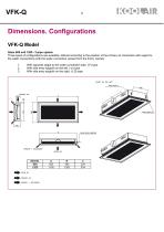
VFK-Q Model Sizes 600 and 1200 - 2-pipe system Three types of configurations are available, defined according to the position of the primary air connection with regard to the water connections (with the water connection viewed from the front), namely: 1. With opposite spigot to the water connection side, (-F) type 2. With side entry spigot/s on the left, (-LI) type 3. With side entry spigot/s on the right, (-LD) type
Open the catalog to page 4
VFK-Q Model Sizes 600 and 1200 - 4-pipe system Three types of configurations are available, defined according to the position of the primary air connection with regard to the water connections (with the water connection viewed from the front), namely: 1. With opposite spigot to the water connection side, (-F) type 2. With side entry spigot/s on the left, (-LI) type 3. With side entry spigot/s on the right, (-LD) type
Open the catalog to page 5
Installation - Chilled beam designs for different types of ceilings All VFK beam sizes are made to be installed in different kinds of false ceilings. - Lay-in grid with T-support section with a width of 25 and 15 mm (1)
Open the catalog to page 6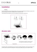
Installation - Fastening The VFK-Q units include a series of hanging brackets on the two upper longitudinal sides of the beams, as shown in the following photographs. There are two brackets per side in sizes 600 and 1200. These brackets are M-8 threaded rod, which is first attached to the ceiling slab to hang the unit. Access rack PLACE THE PIECE “B” ON PIECE “A” AND PUSH TO HEAR “CLICK” REPEAT THIS OPERATION IN ALL CORNERS The induction grille or front perforated rack can be removed by operating small latches on the corners of the beam. This provides access to the interior of the chilled beam...
Open the catalog to page 7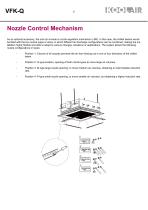
Nozzle Control Mechanism As an optional accessory, the unit can include a nozzle regulation mechanism (-SR). In this case, the chilled beams would be fitted with the two nozzle types or sizes, in which different air discharge configurations can be combined, making the installation highly flexible and able to adapt to various changes, situations or applications. The system allows the following nozzle configurations or types: - Position 1: Closure of all nozzles prevents the air from flowing out in one or four directions of the chilled beam. Position 2: G type-location, opening of both nozzle types...
Open the catalog to page 8
Air deflectors As an optional accessory, the VFK-Q chilled beams can be fitted with air deflector slats (-DF) manufactured of M1 plastic, longitudinally built into the diffusers. By modifying the position, the air jet can be adjusted to different directions, making it a highly flexible unit to adapt to different situations in the installation. This makes it possible to handle obstacles, to broaden the width of the air jet and to slow the velocity of the jet over a specific throw, in short, to ensure an environment free of air currents. Several applications are shown below in the following figures:...
Open the catalog to page 9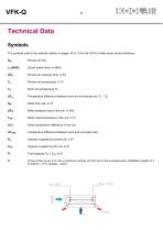
Technical Data Symbols The symbols used in the selection tables on pages 10 to 13 for the VFK-Q chilled beam are the following: Qpr Primary air flow Lw-dB(A) Sound power level, in dB(A) APpr Primary air pressure drop, in Pa ATpr Temperature difference between room air and primary air (TR - Tpr) QW Water flow rate, in l/h APW Water pressure drop in the coil, in kPa TWIN Water inlet temperature in the coil, in °C ATW Water temperature difference in the coil ATSWIN Temperature difference between room and unit water inlet Ppr Capacity supplied by primary air, in W...
Open the catalog to page 10
VFK-Q Technical Data. Selection Tables COOLING - 2-PIPE SYSTEM Reference water flow (QW) of 250 l/h For other water flow rates, correct the unit capacity (PSw) in the table by the factors listed in the attached table. VFK-Q - 2 PIPES SYSTEM COOLING VFK-Q-600 / VFK-Q-1200 - 2 PIPE SYSTEM - COOLING
Open the catalog to page 11
VFK-QTechnical Data. Selection Tables COOLING - 4-PIPE SYSTEM Reference water flow (QW) of 250 l/h For other water flow rates, correct the unit capacity (PSw) in the table by the factors listed in the attached table. VFK-Q - 4 PIPES SYSTEM COOLING VFK-Q-600 / VFK-Q-1200 - 4 PIPE SYSTEM - COOLING
Open the catalog to page 12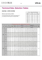
VFK-Q Technical Data. Selection Tables HEATING - 2-PIPE SYSTEM Reference water flow (QW) of 250 l/h For other water flow rates, correct the unit capacity (PSw) in the table by the factors listed in the attached table. VFK-Q - 2 PIPES SYSTEM HEATING VFK-Q-600 / VFK-Q-1200 - 2 PIPE SYSTEM - HEATING
Open the catalog to page 13
VFK-QTechnical Data. Selection Tables HEATING - 4-PIPE SYSTEM Reference water flow (QW) of 250 l/h For other water flow rates, correct the unit capacity (PSw) in the table by the factors listed in the attached table. VFK-Q - 4 PIPES SYSTEM HEATING VFK-Q-600 / VFK-Q-1200 - 4 PIPE SYSTEM - HEATING
Open the catalog to page 14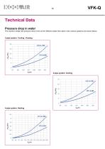
Technical Data Pressure drop in water The charts to obtain the pressure drop in the coil for different water flow rates in the various systems are shown below: 2-pipe system. Cooling - Heating
Open the catalog to page 15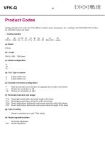
VFK-QProduct Codes Coding example of an order. All of the different models, sizes, accessories, etc., existing in the KOOLAIR VFK-Q active chi- lled beam series are listed. - - Coding example (d): Coil. Type of system - 2 2-pipe system coil (e): Air/water connection configuration - F Rear face primary air connection, on opposite side as water connections - LI Primary air connection on left - LD Primary air connection on right (f): Perforated induction rack design - P1H Rectangular perforations along the length of the beam - P1V Rectangular perforations along the width of the beam - P2H Round...
Open the catalog to page 16All KOOLAIR S.A catalogs and technical brochures
 series FLOOR
23 Pages
 series Dampers 100-2
21 Pages
 FIRE protection
2 Pages
 KOOLCOM
2 Pages
 DFRE-P
1 Page
 PE-45
PE-451 Page
 Acoustic
2 Pages
 Series 100-200 Dampers
18 Pages
 VENTILATION HOODS
6 Pages
 Series SF Fire dampers
35 Pages
 Series SCDC Smoke dampers
11 Pages
 36-STE
2 Pages
 DTP-GT Multi-nozzles diffusers
15 Pages
 DTP Multi-nozzles diffusers
14 Pages
 Koolair product range
2 Pages
 Technical Selection Guide
145 Pages
 Bypass terminal units – KMSR
15 Pages
 Terminal units with fan – HVFS
12 Pages
 Air Volume Boxes – Series KD
7 Pages
 Measurement Station – EM
6 Pages
 Passive chilled beams – VPK
9 Pages
 Induction terminal units – IHK
20 Pages
 Square diffusers – Series 50
22 Pages
 Multinozzles diffusers – DF49MT3
20 Pages
 Long-throw nozzles – DF 89
19 Pages
 Long-throw nozzles – DF 49
19 Pages
 Linear grilles – Series 30
19 Pages
 S26
S261 Page
 21-DVC/21-DVR
1 Page
 21-SVC/21-SVR
1 Page
 20-SH/21-SH
1 Page
 20-DH/21-DH
1 Page
 Circular diffusers – DCL
2 Pages
 Extract valves – Series GPD
8 Pages
 Circular diffusers – Series 40.1
31 Pages
 Security grilles – KSG
12 Pages
 Return grilles – Series 20.2
19 Pages
 Supply grilles – Series 26
10 Pages
 Regulating dampers
18 Pages
 Silencers – Series SK
25 Pages
 Linear Diffusers – Series 70.1
26 Pages
 Circular diffuser – Series 40.1
31 Pages
 Supply grilles – Series 20.1
19 Pages