- Catalogs
- KOOLAIR S.A
- Active chilled beams – Series VFK 300
Active chilled beams – Series VFK 300
1 /23Pages

Active chilled beams – Series VFK 300
1 /23Pages
Catalog excerpts
VFK 300 Active chilled beams
Open the catalog to page 1
CONTENTS Model VFK 300 General Characteristics 2
Open the catalog to page 2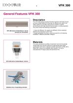
General Features VFK 300 Description The VFK 300 ceiling-mounted induction terminal units (also known as active chilled beams) for two-way air diffusion are used in airwater systems to provide a high level of comfort in interior environments with high internal thermal loads in cooling operation. The units include the following components: VFK 300 Active Chilled Beam, lateral primary air connection - Linear slot diffusers, for supply and diffusion of the combined primary and induced air to the room. - Hinged perforated front face, used as access for unit cleaning. Available in different perforation...
Open the catalog to page 3
2 or 4-pipe system Five types of configurations are available, defined according to the position of the primary air connection with regard to the water connections (with the water connection viewed from the front), namely: 1. Lateral primary air connection on left side, (-LI) type 2. Lateral primary air connection on right side, (-LD) type 3. Primary air connection at top, (-S) type The 900 to 1800 sizes are manufactured with one primary air connection inlet. The beam width measurement (595) listed corresponds to the ceiling-mounted design using a T-section with a width of 25 mm. For installations...
Open the catalog to page 4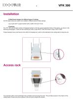
Installation - Chilled beam designs for different types of ceilings All VFK beam sizes are made to be installed in different kinds of false ceilings. - Lay-in grid with T-support section with a width of 25 and 15 mm - Fastening The VFK 300 units include a series of hanging brackets on the two upper longitudinal sides of the beams, as shown in the following photographs. There are two brackets per side in sizes 900 to 1800 and three in sizes 2100 to 3000. These brackets have a slot hole to hold a Ø6 mm threaded rod, which is first attached to the ceiling slab to hang the unit. Access rack The induction...
Open the catalog to page 5
Symbols The symbols used in the selection tables on page 6 to 17 for the VFK 300 chilled beam are the following: Qpr Primary air flow Lw-dB(A) Sound power level, in dB(A) APpr Primary air pressure drop, in Pa ATpr Temperature difference between room air and primary air (TR - Tpr) QW Water flow rate, in l/h APW Water pressure drop in the coil, in kPa TWIN Water inlet temperature in the coil, in °C ATW Water temperature difference in the coil ATSWIN Temperature difference between room and unit water inlet Ppr Capacity supplied by primary air, in W PSW Capacity...
Open the catalog to page 6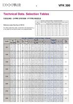
Technical Data. Selection Tables COOLING - 2-PIPE SYSTEM - P-TYPE NOZZLE Reference water flow (QW) of 250 l/h For other water flow rates, correct the unit capacity (PSw) in the table by the factors listed in the attached table. VFK 300 - 2-PIPE SYSTEM - COOLING SYSTEM
Open the catalog to page 7
COOLING - 2-PIPE SYSTEM - M-TYPE NOZZLE Reference water flow (QW) of 250 l/h For other water flow rates, correct the unit capacity (PSw) in the table by the factors listed in the attached table. VFK 300 - 2-PIPE SYSTEM - COOLING SYSTEM VFK 300 - M NOZZLE - 2-PIPE SYSTEM - COOLING
Open the catalog to page 8
Technical Data. Selection Tables COOLING - 2-PIPE SYSTEM - G-TYPE NOZZLE
Open the catalog to page 9
COOLING - 4-PIPE SYSTEM - P-TYPE NOZZLE
Open the catalog to page 10
VFK 300 Technical Data. Selection Tables COOLING - 4-PIPE SYSTEM - M-TYPE NOZZLE
Open the catalog to page 11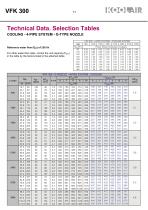
VFK 300Technical Data. Selection Tables COOLING - 4-PIPE SYSTEM - G-TYPE NOZZLE
Open the catalog to page 12
VFK 300 Technical Data. Selection Tables HEATING - 2-PIPE SYSTEM - P-TYPE NOZZLE
Open the catalog to page 13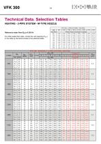
VFK 300Technical Data. Selection Tables HEATING - 2-PIPE SYSTEM - M-TYPE NOZZLE
Open the catalog to page 14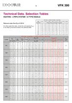
VFK 300 Technical Data. Selection Tables HEATING - 2-PIPE SYSTEM - G-TYPE NOZZLE
Open the catalog to page 15
VFK 300Technical Data. Selection Tables HEATING - 4-PIPE SYSTEM - P-TYPE NOZZLE Reference water flow (QW) of 50 l/h for sizes 600 to 1800. Reference water flow (QW) of 110 l/h for sizes 2100 to 3000. For other water flow rates, correct the coil capacity (PSw) in the table by the factors listed in the attached table. VFK 300 - P NOZZLE - 4-PIPE SYSTEM - HEATING
Open the catalog to page 16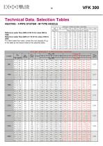
VFK 300 Technical Data. Selection Tables HEATING - 4-PIPE SYSTEM - M-TYPE NOZZLE Reference water flow (QW) of 50 l/h for sizes 600 to 1800. Reference water flow (QW) of 110 l/h for sizes 2100 to 3000. For other water flow rates, correct the coil capacity (PSw) in the table by the factors listed in the attached table. VFK 300 - M NOZZLE - 4-PIPE SYSTEM - HEATING
Open the catalog to page 17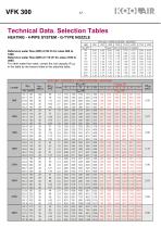
VFK 300Technical Data. Selection Tables HEATING - 4-PIPE SYSTEM - G-TYPE NOZZLE Reference water flow (QW) of 50 l/h for sizes 600 to 1800. Reference water flow (QW) of 110 l/h for sizes 2100 to 3000. For other water flow rates, correct the coil capacity (PSw) in the table by the factors listed in the attached table.
Open the catalog to page 18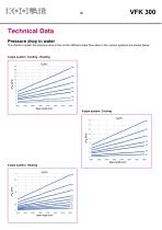
Technical Data Pressure drop in water The charts to obtain the pressure drop in the coil for different water flow rates in the various systems are shown below: 2-pipe system. Cooling - Heating
Open the catalog to page 19
VFK 300Product Codes Coding example of an order. All of the different models, sizes, accessories, etc., existing in the KOOLAIR VFK 300 active chilled beam series are listed. - Coding example (d): Coil Type of system. - 2 2-pipe system coil (e): Air/water connection configuration - LI Primary air connection on left - LD Primary air connection on right - S Primary air connection at top (f): Perforated induction rack design - P1H Rectangular perforations along the length of the beam - P1V Rectangular perforations along the width of the beam - P2H Round perforations distributed continuously...
Open the catalog to page 20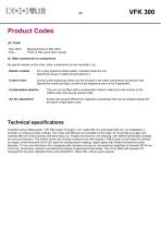
Product Codes (h): Finish - RAL 9010 - RAL … Standard finish in RAL 9010 Finish in RAL paint upon request (i): Other accessories or components By special request on the order, other components can be requested, e.g.: - Electric resistor For 2-pipe systems (chilled water), included inside the unit. Specify the power in watts (W) provided by it. - Control valve Control and/or balancing valves can be included in the water connections by special order. Specify the model and type, as well as the respective servo drive if applicable. - Condensation detector The unit can be fitted with a condensation...
Open the catalog to page 21All KOOLAIR S.A catalogs and technical brochures
 series FLOOR
23 Pages
 series Dampers 100-2
21 Pages
 FIRE protection
2 Pages
 KOOLCOM
2 Pages
 DFRE-P
1 Page
 PE-45
PE-451 Page
 Acoustic
2 Pages
 Series 100-200 Dampers
18 Pages
 VENTILATION HOODS
6 Pages
 Series SF Fire dampers
35 Pages
 Series SCDC Smoke dampers
11 Pages
 36-STE
2 Pages
 DTP-GT Multi-nozzles diffusers
15 Pages
 DTP Multi-nozzles diffusers
14 Pages
 Koolair product range
2 Pages
 Technical Selection Guide
145 Pages
 Bypass terminal units – KMSR
15 Pages
 Terminal units with fan – HVFS
12 Pages
 Air Volume Boxes – Series KD
7 Pages
 Measurement Station – EM
6 Pages
 Passive chilled beams – VPK
9 Pages
 Induction terminal units – IHK
20 Pages
 Square diffusers – Series 50
22 Pages
 Multinozzles diffusers – DF49MT3
20 Pages
 Long-throw nozzles – DF 89
19 Pages
 Long-throw nozzles – DF 49
19 Pages
 Linear grilles – Series 30
19 Pages
 S26
S261 Page
 21-DVC/21-DVR
1 Page
 21-SVC/21-SVR
1 Page
 20-SH/21-SH
1 Page
 20-DH/21-DH
1 Page
 Circular diffusers – DCL
2 Pages
 Extract valves – Series GPD
8 Pages
 Circular diffusers – Series 40.1
31 Pages
 Security grilles – KSG
12 Pages
 Return grilles – Series 20.2
19 Pages
 Supply grilles – Series 26
10 Pages
 Regulating dampers
18 Pages
 Silencers – Series SK
25 Pages
 Linear Diffusers – Series 70.1
26 Pages
 Circular diffuser – Series 40.1
31 Pages
 Supply grilles – Series 20.1
19 Pages


- Ventilation grill
- Metal ventilation grill
- Rectangular ventilation grill
- Industrial air diffuser
- Square ventilation grill
- Ceiling-mounted air diffuser
- White ventilation grill
- Home ventilation grill
- Circular displacement air diffuser
- Square air diffuser
- Interior ventilation grill
- Ventilation damper
- Air filter
- Linear air diffuser
- Adjustable ventilation grill
- Metal ventilation damper
- Slot air diffuser
- Linear ventilation grill
- Stainless steel ventilation grill
- Industrial jet nozzle