Catalog excerpts
I M P R int © KLH Massivholz GmbH Publisher and responsible for the content: KLH Massivholz GmbH Version: 01/2011, Component Catalogue for Industrial Buildings The content of this brochure is intellectual property of the company and is protected by copyright. The statements are recommendations and proposals only; a liability on the part of the publisher is excluded. Any type of reproduction is strictly forbidden and only permitted after written approval of the publisher.
Open the catalog to page 2
INDUSTRIAL bUILDINGS With KLH solid wood panels it is certainly possible to create simple and also economical construction systems for industrial buildings, halls and the like. In combination with a primary support structure, e.g. made of steel or laminated timber, even large spans can be bridged without supporting columns. With KLH solid wood panels industrial buildings can be designed completely in wood, from the foundation edge upwards. Halls with a length of up to 100 m have been constructed in this way. In the interior, the KLH solid wood panels are usually left exposed. The result of...
Open the catalog to page 4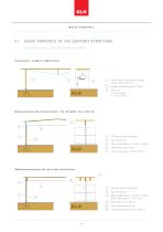
BASIC PRINCIPLE Basic principle of the support structure 1.1 Overvie w of hall and industrial buildings Trussed panel – straight or slightly curved Erected KLH panels as wall (height approx. 400 to 500 cm) Height of trussing approx. L/16th KLH wall panels horizontally Skeleton structure with laminated timber – flat roof, gable roof or shed roof Beam height approx. L/15th to L/20th Laminated timber column Column grid approx. 400 to 550 cm KLH wall panels horizontally Beam height approx. L/25th to L/35th, panel height approx. 10 to 15 cm Laminated timber column Column grid approx. 400 to 550...
Open the catalog to page 6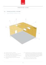
PENDULOUS WALL SYSTEM PENDULOUS WALL SYSTEM Pendulous wall system of a hall Roof panels transverse to roof girders Roof support system possible in varied forms: gable roof, curved girders, shed roof, trussed systems, etc. Choose a rather narrow roof girder distance; this way very thin roof panels (6 to 8 cm) are possible Roof girders are fitted into wall niches (no steel parts necessary) Gable wall as a load-bearing component Solid exterior walls for hall heights of 5 to 8 m; with wall thicknesses of 20 cm and more, also R90 fire resistance rating can be attained; 20 cm thick timber walls...
Open the catalog to page 7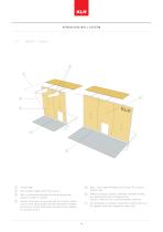
PENDULOUS WALL SYSTEM Canopy edge Caution: KLH panels are only approved for utilisation classes 1 and 2; if the canopy protects the wall sufficiently (30-degree line from the canopy to the base), the wall can be assigned to utilisation class 2 Without a canopy a façade is definitely necessary outside, e.g. metal façade, poly carbonate panels Caution: Paints are not a sufficient weather protection With a sufficiently projecting roof also an exterior wall without a façade is possible Base – lower edge of wooden parts at least 30 cm above external level Set roof girders as cantilever towards...
Open the catalog to page 8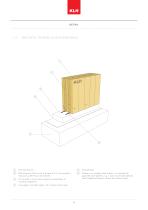
2.3 BASE DETAIL FOR MORE SOLID EXTERIOR WALLS (T) KLH wall element (?) Concrete base (¥) Wall thickness of 20 cm has a U-value of 0.5, fire resistance @ If there is no insulation level outside, it is important to rating of e.g. REI 90 can be achieved guarantee joint tightness, e.g. 2 rows of joint tapes (directly (3) Put sill plate in mortar bed, tolerance compensation to under longitudinal layers); caution with vertical joints! concrete components (4) Lower edge of sill plate approx. 30 m above external leve
Open the catalog to page 9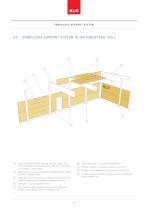
PENDULOUS SUPPORT SYSTEM Pendulous support system of an industrial hall Adjust roof panels to roof load and axis grid; panels up to 12 cm thickness are still economical, make use of the effect of continuity (3-span girder) Roof support system possible in varied forms: gable roof beams, curved girders, trussed roof girders, etc. Wooden columns in distances of approx. 4 to 5.5 m Columns in the gable wall also in distances of 4 to 6 m Roof girder, e.g. of laminated timber Wall panel horizontally oriented to deflect wind forces and for building reinforcement, thicknesses approx. 8 to 10 cm...
Open the catalog to page 10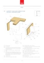
Support structure connections for hall constructions 1 3 Connection between column and girder Screw connection of the ceiling panels with the wall panels – transfer of forces from the roof section to the wall section (building reinforcement) E.g. steel part for transmission of horizontal forces by means of self-drilling SFS dowel pins Suction anchoring of the walls in the columns by means of SFS or fully threaded screws Levelling of height difference using hardwood or metal Protection against rising moisture Steel bracket – deflection of wind forces that have a direct effect on the walls in...
Open the catalog to page 11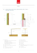
Detail base point and longitudinal wall joint – vertical section Wall structure Façade – metal sheet/wood/cement-bound chipboard Back ventilation Insulation between the battens (8 cm insulation U = 0.35 W/(m 2K)) KLH wall panel (approx. 60 to 108 mm with column distance of approx. 400 to 550 cm) Moisture sealing E.g. prefabricated concrete component with insulating core and exposed concrete outside Level inside Upper edge of ground outside 30 cm protection against water splash S10 square timber (approx. 8/8) Self-drilling wood screw Nailing or screwing (according to static requirement)...
Open the catalog to page 12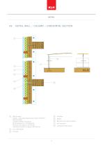
Detail wall – column – horizontal section Wall structure Façade – metal sheet/wood/cement-bound chipboard Back ventilation Insulation between the battens (8 cm insulation U = 0.35 W/(m 2K)) KLH wall panel (approx. 60 108 mm with column distance of approx. 400 550 cm) Butt joint of the panel elements Laminated timber column
Open the catalog to page 13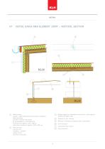
Detail e aves and element joint – vertical section Stütze aus BS-Holz KLH Wandplatten 7 Wall structure Façade – metal sheet/wood/cement-bound chipboard Back ventilation Insulation between the battens (8 cm insulation U = 0.35 W/(m²K)) KLH wall panel (approx. 60 to 108 mm with column distance of approx. 400 to 550 cm) Nailing or screwing (according to static requirement) Laminated timber column Stütze for joint Plywoodaus BS-Holzcovering Roof structure E.g. film roof Insulation – loadable Vapour barrier KLH solid wood panel Shiplap edge as an alternative to butt board – particularly of...
Open the catalog to page 14All KLH Massivholz catalogs and technical brochures
-
RIB ELEMENTS
20 Pages
-
STRUCTURAL PRE-ANALYSIS TABLES
32 Pages
-
WCTE_2016_Special
35 Pages
-
Wooden feelings
13 Pages
-
Environment and Sustainability
40 Pages
-
Assembly & Installation
28 Pages
-
Building Physics
32 Pages
-
Lifting Systems
28 Pages
-
Cross-laminated Timber
20 Pages
Archived catalogs
-
Mission Statement
8 Pages


