- Catalogs
- KLH Massivholz
- Component catalogue for cross laminated timber structures

Component catalogue for cross laminated timber structures

Component catalogue for cross laminated timber structures
Steel components are utilized to manage high bearing forces in shear walls, ensuring direct force transfer across the grain. KLH wall and ceiling panels are engineered based on static requirements, with options for either steel or wooden supports. Metal plates aid in force transfer across grains, and screw connections are specified to be spaced at a maximum of 10 to 15 cm.
Sealing layers should be connected using approved products. An external sealing layer may eliminate the need for sealing tape. The façade construction includes a convection barrier, with a windproof, diffusion-permeable membrane applied externally. Detailed attention is given to ceiling joints and base connections, highlighting the importance of joint tapes for maintaining air-tightness.
KLH panels function as an inner air-tight layer, necessitating joint tapes for all panel joints. Sealing tapes are applied transversely to shiplap edges, and screw connections are made according to static requirements. Transverse ceiling joints also require joint tapes to ensure air-tightness.
Slots and boreholes in wood surfaces must follow specific guidelines, maintaining minimum distances to edges and requiring static analysis for certain areas. Vertical slots are permitted only in the direction of the covering layer fibers.
Slots in roof panels with visible wooden soffits and ceilings must be meticulously planned, with static analysis necessary. Openings for cable routes should be divided with bars if they are placed at an angle to the ceiling span direction.
Catalog excerpts

IMPRINT © KLH Massivholz GmbH Publisher and responsible for the content: KLH Massivholz GmbH Version: 01/2011, Component Catalogue for Cross laminated timber Structures The content of this brochure is intellectual property of the company and is protected by copyright. The statements are recommendations and proposals only; a liability on the part of the publisher is excluded. Any type of reproduction is strictly forbidden and only permitted after written approval of the publisher.
Open the catalog to page 2
The suggested constructional designs with KLH solid wood panels show application details in a systematic and self-explanatory form. cellulose, etc. as well as different façade materials on back-ventilated façades or rendered façades. The structural and physical aspects such as sound insulation, heat insulation, air tightness of the building or fire protection must be assessed on the basis of the relevant project. Users and planners will be able to easily derive projectspecific details with reference to the basic depictions. The suggested detailed solutions merely represent recommendations given...
Open the catalog to page 4
Architect Dipl. Ing. Huber t Rieß,
Open the catalog to page 5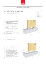
WALL- CONCRETE CONNECTION WALL- CONCRETE CONNECTION WITHOUT ADDITIONAL SILL PLATE KLH wall panel according to static requirements E.g. BMF angle bracket Shear transmission and tension anchorage for the walls according to static requirements The walls must rest on the base over their entire length – if the walls only rest on the base in some places, static verification is required Caution: At least 2 dowels must be installed for each BMF angle bracket; otherwise the effect of the angle bracket is highly reduced (preferably use the two holes directly next to the wall or the sill plate) Concrete...
Open the catalog to page 6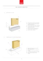
WALL- CONCRETE CONNECTION WITH HIGH SILL PLATE KLH wall panel according to static requirements E.g. BMF perforated plate for shear connection between KLH wall and sill Concrete component (wall, ceiling, concrete slab) Concrete screws for shear force transmission between sill and concrete Oak or larch sill laid in mortar bed – with the entire surface resting on the base Install joint tape, if necessary Diagonal fully threaded screws to absorb higher horizontal forces Sill plate laid in mortar bed and dowelled to concrete CONNECTION OF THICKER EXTERIOR WALLS 2 x sealing tape along longitudinal...
Open the catalog to page 7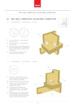
WALL-WALL CONNECTION, CEILING -WALL CONNECTION WALL-WALL CONNECTION, CEILING-WALL CONNECTION 2.1 EXTERIOR WALL – INTERIOR WALL - CEILING Cross wall connection – screw connection from the outside Cross wall connection – screw connection from the inside Shear force transmission along the joint and tension anchorage of walls – e.g. BMF angle bracket – type, distance according to static requirements Screw connection of ceiling with walls according to static requirements 2.2 EXTERIOR WALL – EXTERIOR WALL - CEILING Corner joint – screw connection of wall corners according to static requirements or...
Open the catalog to page 8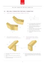
WALL-WALL CONNECTION, ROOF-WALL CONNECTION WALL-WALL CONNECTION, ROOF-WALL CONNECTION CONNECTIONS OF WALLS AT AN ANGLE TOWARDS EACH OTHER For very shallow angles, the effectiveness of screw connections is quite limited; special measures might become necessary The screws only transfer shear forces in the direction of the joints; mind the reduced bedding lengths Bevelled panel edges can only be easily produced up to approx. 20 cm of bevelled length Required edge distances for the screws Shiplap design if high shear forces must be transferred 3.2 EAVES DESIGN WITH CANOPY OR INTERMEDIATE BEARING...
Open the catalog to page 9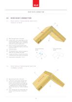
ROOF- ROOF CONNECTION ROOF- ROOF CONNECTION 4.1 RIDGE DESIGN, IF MAIN BEARING DIRECTION IS PARALLEL TO RIDGE Main bearing direction of the panel Caution: Bevel cut for panel edges can only be easily produced up to 20 cm of bevelled length; greater lengths require considerably more work on beams (higher costs) Screw connection mainly transfers shear forces in a longitudinal direction, only minor transverse forces Transverse forces The transverse forces of this joint design are higher than for bevelled panel edges If panels are thinner, it may not be possible to transfer forces with screws (cross...
Open the catalog to page 10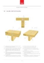
CEILING JOINT ON THE WALL CEILING JOINT ON THE WALL Take construction tolerances into consideration for bearing width Ceiling joint over a thin wall (may be necessary for soundtechnical decoupling of roof panels) Bearing width at least 4 cm; keep compression normal in relation to fibre. Keep in mind fire stress: approx. 3 cm; bearings must still be in place even after wall has burnt down Shear force transmission from panel to panel Alternating niches in panel ends Width of niche depends on panel type – thin cross layers require shorter distances Bearing in niche, fully effective for the panel...
Open the catalog to page 11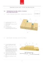
TR ANSVERSE CEILING JOINTS, FLEXIBLE AND BEND - RESISTANT 6.1 FLEXIBLE TRANSVERSE CEILING JOINTS – STANDARD WIDTH CONNECTION Connection for shear transmission in the direction of the joint Install joint tape, if air tightness is required (e.g. fire, smoke) Plywood strip Type, diameter and distance of screw connection according to static requirements 6.2 BEND - RESISTANT LONGITUDINAL JOINT FOR THIN PANELS In case of roof panels, vapour barriers should be installed below the coupling piece A fairly cost-effective type of bend-resistant joint; high load-bearing capacities can also be achieved without...
Open the catalog to page 12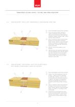
6.3 BEND - RESISTANT CROSS JOINT ( TRANSVERSE TO MAIN BEARING DIRECTION) Use is only practical where transverse rigidity is absolutely necessary; gluing should only be performed under controlled conditions (climate, surfaces, staff) – and is therefore rather expensive Glue on connection straps (screw-pressure gluing) or only mechanical connection (nails, screws); materials: veneer laminated timber or 3s panels or according to static requirements; relatively high transmission forces are possible Effective cross-section height in cross direction Forces transferable by way of the connection Transverse...
Open the catalog to page 13All KLH Massivholz catalogs and technical brochures
 RIB ELEMENTS
20 Pages
 STRUCTURAL PRE-ANALYSIS TABLES
32 Pages
 WCTE_2016_Special
35 Pages
 Wooden feelings
13 Pages
 Environment and Sustainability
40 Pages
 Assembly & Installation
28 Pages
 Building Physics
32 Pages
 Cross-laminated Timber
20 Pages
 Lifting Systems
28 Pages




Archived catalogs
 Mission Statement
8 Pages