WorkZone® Desking System
1 /36Pages

WorkZone® Desking System
1 /36Pages
Catalog excerpts

Assembly Instructions WorkZone® Desking System
Open the catalog to page 1
■ WorkZone® Basic Worksurface Assembly Instructions AAssemble units as described herein only. To do otherwise may result in instability. All screws, nuts and bolts must be tightened securely and must be checked periodically after assembly. Failure to assemble properly, or to secure parts Q^JJ"T| Q|\| maYresu" 'n assembly failure and personal injury Tools Required • Phillips Screwdriver worksurface, place the top face down onto a soft protective aligning legs to pre-drilled holes and inserting three Note: In the instance where with a transitional unit, a leg set with a short transitional foot...
Open the catalog to page 2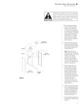
WorkZone® Basic Worksurface Assembly Instructions Assemble units as described herein only. To do otherwise may result in instability. All screws, nuts and bolts must be tightened securely and must be checked periodically after assembly. Failure to assemble properly, or to secure parts may result in assembly failure and personal injury. sic Worksurface / Printer Stand anel between leg sets. l wireway is to be ce the wireway lange of modesty surface, aligning the llustrated. Insert two per left and right side to leg. Do not tighten 1). 3. Align modesty panel between leg sets. If optional horizontal...
Open the catalog to page 3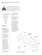
WorkZone® Starter/Adder/Finisher Worksurface Assembly Instructions Assemble units as described herein only. To do otherwise may result in instability. All screws, nuts and bolts must be tightened securely and must be checked periodically after assembly. Failure to assemble properly, or to secure parts may result in assembly failure and personal injury. the illustrated location, in the set of three mounting holes using three #12 x 1 3/4” screws (Figure 1). Note: Starter/finisher modesty panels are longer than standard WorkZone modesty panels, and are shorter than adder modesty panels. Tools Required...
Open the catalog to page 4
WorkZone® Starter/Adder/Finisher Worksurface Assembly Instructions Assemble units as described herein only. To do otherwise may result in instability. All screws, nuts and bolts must be tightened securely and must be checked periodically after assembly. Failure to assemble properly, or to secure parts may result in assembly failure and personal injury. Adder Worksurface Note: The adder worksurface is assembled upside down, and when turned upright after full assembly, it will attach to the worksurface to its right (either starter or adder as the user sits at it). Starter/Adder/Finisher Worksurface...
Open the catalog to page 5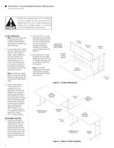
WorkZone® Starter/Adder/Finisher Worksurface Assembly Instructions Assemble units as described herein only. To do otherwise may result in instability. All screws, nuts and bolts must be tightened securely and must be checked periodically after assembly. Failure to assemble properly, or to secure parts may result in assembly failure and personal injury. Finisher Worksurface Note: The finisher worksurface is assembled upside down, and when turned upright after full-assembly, it will attach to an adder worksurface. 8. To avoid scratching top, carefully lay finisher worksurface upside down on a soft,...
Open the catalog to page 6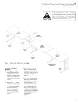
11.Carefullly turn the finisher worksurface assembly to the upright position and set the no-leg end of the Starter/Adder/Finisher Worksurface adder surface onto the shared-leg bracket of theAssembly Instructions adder worksurface assembly (Figure 5). 12. Twist in four #12 x 1” screws through the shared-leg bracket of the Assemble units as described herein only. To do otherwise adder worksurface, and into the premay result in instability. All screws, nuts and bolts must be drilled mounting holes at the underside of tightened securely and must be checked periodically after the finisher worksurface...
Open the catalog to page 7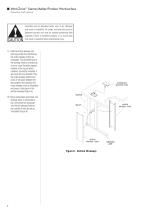
WorkZone® Starter/Adder/Finisher Worksurface Assembly Instructions Assemble units as described herein only. To do otherwise may result in instability. All screws, nuts and bolts must be tightened securely and must be checked periodically after assembly. Failure to assemble properly, or to secure parts may result in assembly failure and personal injury. Starter/Adder/Finisher Worksurface Assembly 15. Install a vertical wireway into each leg set 17. first positioningwireway into by Install a vertical the outer wireway section each leg set by first positioningface as illustrated. The extended the...
Open the catalog to page 8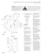
WorkZone® Desks - 24”, 30” x 30” through 54” Tops with Power & Data Assembly Instructions WARNING: Assembly of all mechanical frame components must be completed before making any electrical connections. All electrically connected furnishings must also be mechanically connected. mounting bracket adjustable glide power/data door #10 x ½” screw Assemble units as described herein only. To do otherwise may result in instability. All screws, nuts and bolts must be tightened securely and must be checked periodically after assembly. Failure to assemble properly, or to secure parts may result in assembly...
Open the catalog to page 9
oles. Insert three #12 x 1” screws through e mounting bracket and modesty panel to the worksurface. Tighten all screws to ecure the legWorkZone® panel sets and modesty Desks igure 1). Assembly Instructions Fasten door clips to the underside of the orksurface with two #12 x 1” screws per oor clip (Figure 1). vertical wireway will be replaced by a floor feed vertical wireway which is explained in instructions 14 through 17. 24”, 30” x 30” through 54” Tops with Power & Data 10. If worksurface assemblies are to be ganged, attach them together with #12 x 1” screws at table-totable wireway and splice...
Open the catalog to page 10
WorkZone® Desks - 24”, 30” x 30” through 54” Tops with Power & Data Assembly Instructions Assemble units as described herein only. To do otherwise may result in instability. All screws, nuts and bolts must be tightened securely and must be checked periodically after assembly. Failure to assemble properly, or to secure parts may result in assembly failure and personal injury. WorkZone with Power & Data - Assembly Instructions Note: All table connections must be securely fastened before any electrical connections between worksurfaces can be installed. jumper cable center vertical wireways 13. To...
Open the catalog to page 11All KI catalogs and technical brochures
 Katera
3 Pages
 Sequence
12 Pages
 TASK SEATING SOLUTIONS
12 Pages
 Monitor Arms
3 Pages
 Hub
Hub4 Pages
 Altus
Altus4 Pages
 Strive
2 Pages
 Doni
Doni2 Pages
 MyWay
MyWay8 Pages
 Lyra
Lyra4 Pages
 Jessa
Jessa2 Pages
 Cody Lounge Seating
2 Pages
 600 SERIES CHAIR
1 Page
 Sway Lounge Chair
1 Page
 DATALINK MULTIPURPOSE TABLE
2 Pages
 DATALINK TABLE SYSTEM
4 Pages
 ENLITE TABLE COLLECTION
8 Pages
 FLAT SCREEN GARAGE
2 Pages
 GENESIS ADJUSTABLE DESKING
8 Pages
 HURRY UP TABLE
4 Pages
 INQUIRE TABLE
4 Pages
 INTANDEM TABLE SYSTEM
4 Pages
 PIROUETTE TABLE
4 Pages
 LAPTOP GARAGE
2 Pages
 SMART LIFT
4 Pages
 SYNTHESIS TABLE
4 Pages
 TABLE SOLUTIONS
12 Pages
 TOGGLE ADJUSTABLE TABLE
2 Pages
 TREK TABLE COLLECTION
4 Pages
 WHARTON LECTERN
2 Pages
 WORKUP ADJUSTABLE TABLE
4 Pages
 WorkZone Desking System
4 Pages
 Serenade™
4 Pages
 Promenade®
2 Pages
 Toggle®
2 Pages
 Sela®
Sela®4 Pages
 Modular Power Systems
4 Pages
 Keyboard Accessories
2 Pages
 Isle Power Tower
2 Pages
 Flat Screen Support System
2 Pages
 Connection Zone Screen
2 Pages
 All Terrain Accessories
2 Pages
 Soltíce Metal
8 Pages
 Learn2
7 Pages
 Affina® Collection
12 Pages
 WireWorks Panel System
22 Pages
 System 3000
4 Pages
 arissa
5 Pages
 Versa® Chairs
8 Pages
 U-Series Storage Brochure
4 Pages
 Orlo Table Brochure
4 Pages
 Briar Recliner Brochure
2 Pages
 ROSE 4-LEG
2 Pages
 Laresta Day Bed Brochure
4 Pages
 Soltice Collection Brochure
8 Pages
 Promenade Brochure
2 Pages
 LOGIX SQUARE SEATING
2 Pages
 Wood Casegoods
12 Pages
 Dante Casegoods
4 Pages
 Aristotle
8 Pages
 AMADEUS
4 Pages
 RAPTURE STOOL
2 Pages
 UNIFRAME TABLE W/BENCH
12 Pages
 LANCASTER AUDITORIUM SEATING
2 Pages
 CONCERTO AUDITORIUM SEATING
2 Pages
 ROOMSCAPE FURNITURE
2 Pages
 GENIUS MOVABLE WAL
16 Pages
 LIGHTLINE MOVABLE WALL
12 Pages


Archived catalogs
 Mesa
Mesa2 Pages
 QUICK SHIP PROGRAM
8 Pages
 KI DESIGN COLLECTION
20 Pages
 BLUSKY COLLECTION
34 Pages
 WORKPLACE FACTORS ASSESSMENT
4 Pages
 ChangeUp™ Tablet Arm Chairs
2 Pages
 TORSION AIR
2 Pages
 CALIDA
4 Pages
 Folding Chairs
2 Pages
 Tatto
Tatto12 Pages
 700 Series® Desking System
2 Pages
 Perth®
2 Pages
 Soltíce® Recliners
2 Pages
 Athens® Tables
2 Pages
 Pirouette® Tables
8 Pages
 Torsion
8 Pages
 Allude Task Seating Brochure
2 Pages
 Rose Chair Brochure
2 Pages
 Promenade Brochure
2 Pages
 LED Desktop Light Brochure
2 Pages
 Intellect Wave
8 Pages
 Intellect Classroom Furniture
12 Pages
 SystemsWall Panel Brochure
16 Pages
 True Desk System
12 Pages
 Rapture Seating Brochure
2 Pages
 Piretti seating
2 Pages
 Grand Salon Lounge Brochure
2 Pages
 DuraStack Brochure
2 Pages
 Devon Table Brochure
2 Pages
 Crossroads Library Furniture
6 Pages
 Cafe Stool Collection
2 Pages


