

Catalogue

Catalogue
Catalog excerpts

Konstruktion Die Konstruktion zur Auflage der Bodenplatten besteht aus verzinkten Stahlrohrstützen, die in Fußgelenken gelagert werden. Die C-Profile werden am Stützenkopf mit dem Kreuzverbinder verschraubt. Diese Verschraubung ist nach VDE elektrisch leitend ausgeführt. Die Rastergröße richtet sich nach der geforderten Tragfähigkeit. Die Nivellierung erfolgt stufenlos durch ein Einstellgewinde. Zur Revision oder zum Nachrüsten lassen sich die Bodenplatten und das Rastersystem ganz oder teilweise demontieren. Design The structure for supporting the floor panels consists of zinccoated tubular steel supports which are located in floor plates and are fitted on the head or support plate (cross-connector) with a threaded levelling device permitting a tolerance of ± 30 mm. According to load requirements, the supports are bolted to the C-profiles to form a suitably dimensioned modular system on which floor panels of suitable size are placed. The joint is electrically conductive in accordance with VDE. For inspection or retrofitment, the floor panels and, if necessary, the modular system can be wholly or partly disassembled and reassembled.
Open the catalog to page 1
Konstruktion Die Konstruktion zur Auflage der Bodenplatten besteht aus verzinkten Stahlrohrstützen, die in Fußgelenken gelagert werden. Die C-Profile werden am Stützenkopf mit dem Kreuzverbinder verschraubt. Diese Verschraubung ist nach VDE elektrisch leitend ausgeführt. Die Rastergröße richtet sich nach der geforderten Tragfähigkeit. Die Nivellierung erfolgt stufenlos durch ein Einstellgewinde. Zur Revision oder zum Nachrüsten lassen sich die Bodenplatten und das Rastersystem ganz oder teilweise demontieren. Design The structure for supporting the floor panels consists of zinccoated tubular...
Open the catalog to page 2
Anwendungsbeispiele Schaltschrank-Unterkonstruktionen mit Grundrahmen (Bild 1), Doppelboden-Anlagen mit integriertem Kabeltragsystem (Bild 2), Kabeltragsystem und vertikale Kabelzuführung (Bild 3) Application Switchgear cabinet subsstructure with base frame. (pic. 1), Double-floor systems with integrated cable tray system (pic. 2), Cable tray system and vertical cable feed (pic. 3). Hochverdichtete Mehrschichtenspanplatten oder Mineralstoffplatten. Kunststoff-Umleimer, 0,6 mm dick, leitend/isolierend Aluminiumfeinblech oder Stahlblech, Mineralstoff auch ohne Rückseitenbeschichtung 10 Stahl-Fußgelenk...
Open the catalog to page 3
Anwendungsbeispiele Schaltschrank-Unterkonstruktionen mit Grundrahmen (Bild 1), Doppelboden-Anlagen mit integriertem Kabeltragsystem (Bild 2), Kabeltragsystem und vertikale Kabelzuführung (Bild 3) Application Switchgear cabinet subsstructure with base frame. (pic. 1), Double-floor systems with integrated cable tray system (pic. 2), Cable tray system and vertical cable feed (pic. 3). Hochverdichtete Mehrschichtenspanplatten oder Mineralstoffplatten. Kunststoff-Umleimer, 0,6 mm dick, leitend/isolierend Aluminiumfeinblech oder Stahlblech, Mineralstoff auch ohne Rückseitenbeschichtung 10 Stahl-Fußgelenk...
Open the catalog to page 4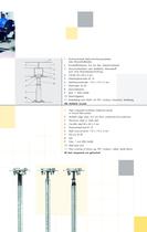
Anwendungsbeispiele Schaltschrank-Unterkonstruktionen mit Grundrahmen (Bild 1), Doppelboden-Anlagen mit integriertem Kabeltragsystem (Bild 2), Kabeltragsystem und vertikale Kabelzuführung (Bild 3) Application Switchgear cabinet subsstructure with base frame. (pic. 1), Double-floor systems with integrated cable tray system (pic. 2), Cable tray system and vertical cable feed (pic. 3). Hochverdichtete Mehrschichtenspanplatten oder Mineralstoffplatten. Kunststoff-Umleimer, 0,6 mm dick, leitend/isolierend Aluminiumfeinblech oder Stahlblech, Mineralstoff auch ohne Rückseitenbeschichtung 10 Stahl-Fußgelenk...
Open the catalog to page 5
Konstruktion Die Konstruktion zur Auflage der Bodenplatten besteht aus verzinkten Stahlrohrstützen, die in Fußgelenken gelagert werden. Die C-Profile werden am Stützenkopf mit dem Kreuzverbinder verschraubt. Diese Verschraubung ist nach VDE elektrisch leitend ausgeführt. Die Rastergröße richtet sich nach der geforderten Tragfähigkeit. Die Nivellierung erfolgt stufenlos durch ein Einstellgewinde. Zur Revision oder zum Nachrüsten lassen sich die Bodenplatten und das Rastersystem ganz oder teilweise demontieren. Design The structure for supporting the floor panels consists of zinccoated tubular...
Open the catalog to page 6
Konstruktion Die Konstruktion zur Auflage der Bodenplatten besteht aus verzinkten Stahlrohrstützen, die mit dem Rohboden verklebt oder verdübelt werden. Die Nivellierung erfolgt stufenlos durch ein Einstellgewinde. Die Bodenplatten werden an ihren Ecken auf den Stützköpfen aufgelegt. Bei höheren Belastungsanforderungen können die Stützköpfe mit Rasterstäben verbunden werden. Zur Revision oder zum Nachrüsten lassen sich die Bodenplatten und die Rasterstäbe demontieren. Zur Ableitung elektrostatischer Aufladungen sind die Stützköpfe mit einer leitfähigen Schalldämmauflage ausgerüstet. Design The...
Open the catalog to page 7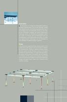
Konstruktion Die Konstruktion zur Auflage der Bodenplatten besteht aus verzinkten Stahlrohrstützen, die mit dem Rohboden verklebt oder verdübelt werden. Die Nivellierung erfolgt stufenlos durch ein Einstellgewinde. Die Bodenplatten werden an ihren Ecken auf den Stützköpfen aufgelegt. Bei höheren Belastungsanforderungen können die Stützköpfe mit Rasterstäben verbunden werden. Zur Revision oder zum Nachrüsten lassen sich die Bodenplatten und die Rasterstäbe demontieren. Zur Ableitung elektrostatischer Aufladungen sind die Stützköpfe mit einer leitfähigen Schalldämmauflage ausgerüstet. Design The...
Open the catalog to page 8
Hochverdichtete Mehrschichtenspanplatten oder Mineralstoffplatten Kunststoff-Umleimer, 0,6 mm dick, leitend/isolierend Aluminiumfeinblech oder Stahlblech, Mineralstoffplatten auch ohne Rückseitenbeschichtung Schalldämmauflage, leitfähig Kopf- oder Trageplatte Rohr, Ø 24 mm x 2 mm Flachmutter zur Arretierung der Höhe 10 Rasterstäbe für höhere Belastungsanforderung 11 Bodenbelag nach Wahl: z.B. PVC, Linoleum, Kautschuk, Textilbelag. Die hochverdichteten Mehrschichtenspanplatten oder Mineralstoffplatten werden im Werk so schablonengefräst, dass sie nach dem Verlegen fugenlos aneinander passen. Die...
Open the catalog to page 9All Kalthoff catalogs and technical brochures
 Prospekt System K1060PB
6 Pages
 Prospect System k3025SB
6 Pages