Install_F_162_F_163_10050789_P03_EU_280918
1 /64Pages

Install_F_162_F_163_10050789_P03_EU_280918
1 /64Pages
Catalog excerpts

PL - Instrukcja montazu i obslugi z danymi technicznymi 49 Manualene ma oppbevares under hele produktets levetid. The manuals which are enclosed with the product must be kept throughout the product’s entire service life. Les manuels fournis avec le produit doivent etre conserves pendant toute la duree de vie du produit. Los manuales suministrados con este producto deben guardarse durante todo el ciclo de vida del producto. I manuali inclusi con il prodotto vanno conservati per l’intera durata di vita del prodotto. Das im Lieferumfang des Produkts enthaltene Begleitmaterial ist uber die gesamte Nutzungsdauer aufzubewahren. De bij de haard meegeleverde handleidingen moeten gedurende de volledige gebruiksduur van de haard bewaard blijven.
Open the catalog to page 1
ENGLISH Installation manual with technical data Installation of a fireplace must be according to local codes and regulations in each country. All local regulations, including those that refer to national and European standards, shall be complied with when installing the product. Before use read the Installation and Operating Instructions carefully. Prior to using the product the installation must be inspected by a qualified person. Register your fireplace at jotul.com for a 25-year warranty. A name plate of heat-resistant material is affixed to the product on the underside of the burnchamber (Fig....
Open the catalog to page 4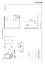
Min. measurements floor plate X,Y = According to national standards and regulations. See chapter 4.1 Hole in floor for external air Ø 100 mm * With semi-insulated chimney / covered flue pipe down towards the product. Min. distance to combustible wall Hole in wall for external air Ø 100 mm Combustible wall
Open the catalog to page 5
Min. distance to combustible wall protected by approved firewall Combustible wall
Open the catalog to page 6
Fig. 2c, through the floor and basement The outside air connection may be fitted directly to the product through: • Through a flexible supply hose from the outside or chimney (only if the chimney has its own duct for external air) and to the product’s outside air connector. Fig. 2a, through an outside wall Important! The knockout for the outside air connection must be removed from the inside. Use safety goggles. Fig. 2d, indirectly through an outside wall Tip: It is a great advantage if the rear leg is dismounted before removing the knockout. 1. Lay the product carefully down on its side. You can...
Open the catalog to page 7
ENGLISH In case of chimney fire: Distance to non combustible walls By non combustible one means a non load-bearing wall of solid brickwork/concrete. Close all hatches and vents. Keep the firebox door closed. Check the loft and cellar for smoke. Call the fire service. Before use after a fire an expert must check the fireplace and the chimney in order to ensure that it is fully functional. 4.0 Installation N.B. Check that the fireplace is free of any damage prior to commencing installation. The product is heavy! Make sure you have assistance when erecting and installing the fireplace. Contact your local...
Open the catalog to page 8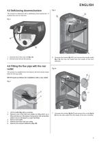
ENGLISH 4.5 Selfclosing doormechanism The product is delivered with a selfclosing doormechanism. If wanted this can be removed. Fig. 3 g 1. Unscrew the screw and nut (fig. 3 A). 2. Unhook and remove the spring. 4.6 Fitting the flue pipe with the rear outlet 6. Unscrew the screws (fig. 5 A) and remove the smoke outlet (fig. 5 B) from the top outlet from the inside of the burn chamber. The product is supplied from the factory with the smoke outlet fitted for the top outlet. NB! Proceed as follows for installation with a rear outlet: Fig. 4 Lift the baffle (Fig. 4 A) up carefully. Remove one of the side...
Open the catalog to page 9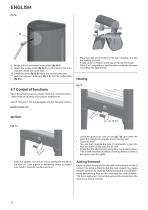
• 8. Knock out the removable cover plates (fig. 6b A). 9. Attach the smoke outlet (fig. 6a A) on the inside of the burn chamber where the cover was. 10. Install the cover (fig. 6a B) where the smoke outlet was. 11. Refit the exhaust deflectors (fig. 4 B) and the baffle plate (fig. 4 A). Place two logs at the bottom of the burn chamber and pile the kindling in layers. Finally, place a medium-sized log on the top of the pile. Place 2 or 3 briquettes or kindling sticks under the top layer of kindling and light the fire. 4.7 Control of functions When the product is set up, always check the control functions....
Open the catalog to page 10
4.7 Danger of overheating The fireplace must never be used in a manner that causes overheating Overheating occurs when there is too much fuel and/or too much air so that too much heat develops. A sure sign of overheating is when parts of the fireplace glow red. If this happens, reduce the air vent opening immediately. Seek professional advice if you suspect that the chimney is not drawing properly (too much/too little draught). For further information, see «4.0 Installations (Chimney and flue pipe). 5.0 Daily use Odours when using the fireplace for the first time When the fireplace is used for...
Open the catalog to page 11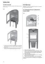
ENGLISH 5.2 Ash removal Jøtul F 162 / F 163 have an ash pan which makes it easy to remove the ash. Fig. 8 6.0 Service Warning! Any unauthorised change to the product is not allowed. Only use original spare parts. 6.1 Changing the burn plates/inner bottom plate Fig.9 1. Scrape the ash through the grate (fig. 8 A) in the base plate and into the ash pan. Use a glove to grab the handle on the ash pan. 1. Make sure that the ash pan doesn’t fill up so high that it keeps ash from coming through the grate into the pan. Lift the baffle (Fig. 9 A) up carefully. Remove one of the side burn plates (Fig. 9 E)...
Open the catalog to page 12
ENGLISH 6.2 Changing the baffle plate Follow step 1 -3 under Fig. 9. Access is then easy to the smoke deflectors (Fig. 9 B) if they need to be removed. They are situated on 1 knob on the side and on the air manifold (fig. 9 D). • Edge them down and remove them through the door. For re-installation follow the same procedure in the opposite sequence. Jøtul recommends that you carefully inspect your fireplace yourself after it has been swept/cleaned. Check all visible surfaces for cracks. Also check that all joints are sealed and that the gaskets are in the correct position. Any gaskets showing signs...
Open the catalog to page 13All Jøtul catalogs and technical brochures
 DoP_F_145-CPR-160617_UK
2 Pages
 Manual_JOTUL_F 230
24 Pages
 Manual_F 360 Advance
88 Pages
 F 360_EU
1 Page

Archived catalogs
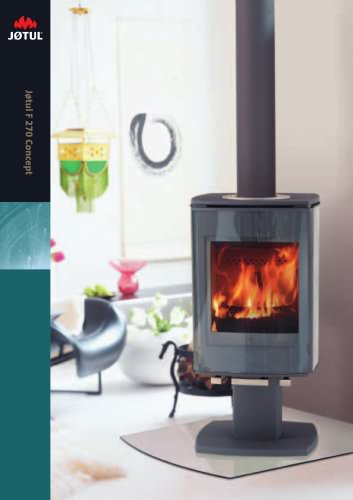
 Jøtul F 270 Concept
12 Pages
 F270 UK September 2005
12 Pages
 CastIron Stoves & Fireplaces
60 Pages


- Contemporary heating stove
- Metal heating stove
- Contemporary fireplace
- Wood heating stove
- Black heating stove
- Single-sided fireplace
- Wood-burning fireplace
- Insert
- Open fireplace
- Cast iron heating stove
- Wood-burning fireplace insert
- Traditional heating stove
- Steatite heating stove
- Outdoor fireplace
- Floor-mounted fireplace
- 3-sided heating stove
- 8 kW heating stove
- Log holder
- Corner fireplace insert