- Catalogs
- ISOTEX SRL
- Operative assembly manual (worldwide)
- Company
- Products
- Catalogs
- News & Trends
- Exhibitions
Operative assembly manual (worldwide)
1 /40Pages

Operative assembly manual (worldwide)
1 /40Pages
Catalog excerpts

OPERATIVE ASSEMBLY MANUAL THE CONSTRUCTION SYSTEM THAT COMBINES QUALITY, SAFETY, SPEED OF INSTALLATION AND COST REDUCTION EUROPEAN LEADER FOR OVER 30 YEARS
Open the catalog to page 1
THE CONSTRUCTION SYSTEM WHICH MARRIES REINFORCED CONCRETE, THE MOST SOLID STRUCTURE, WITH MINERALIZED WOOD, A NATURAL MATERIAL FROM A THOUSAND RESOURCES. The residential district of Fidenza (PR) The Capo Coda Cavallo Hotel Project (NU) Multi-floor buildings in Bologna In 1985, ISOTEX started to produce and market wood-concrete blocks in Italy, after this construction system had been already used in Germany since 1946. From that day on, some 400.000 dwellings have been built with ISOTEX all over Europe, of which some 80.000 in Italy alone, meeting with the approval of specialists, builders and...
Open the catalog to page 2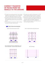
CORRECT TRANSFER OF PACKS FROM THE VEHICLE TO THE GROUND 1. The packs are transferred one at a time, using equipment and procedures in full compliance with current applicable Standards on safety; 2. The packs are moved by insertion of the appropriate equipment into the first row of blocks through the whole depth of the pack itself (see figure); 3. The movement is carried out while avoiding brusque and sudden displacements; 4. The packs are rested on the ground, on a flat surface without changes of level or roughness; 5. Do not stack more than 2 packs on the ground; 6. Movement of packs on the...
Open the catalog to page 4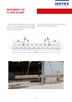
MOVEMENT OF FLOOR SLABS The lifting points of flooring panels are identified in red on the panels themselves, and lifting must be carried out with four chains of suitable length (as in the illustration). Movement operations must always comply with current applicable safety Standards.
Open the catalog to page 5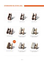
Block HDIII 30/7 graphite (BASF-NEOPOR ) Block HDIII 33/10 graphite (BASF-NEOPOR ) Block HDIII 38/14 graphite (BASF-NEOPOR ) Block HDIII 44/20 graphite (BASF-NEOPOR ) Block HDIII 38/14 cork
Open the catalog to page 6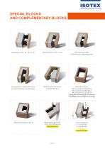
SPECIAL BLOCKS AND COMPLEMENTARY BLOCKS Universal block (UNI) of 38-44 cm for external corners Universal block (UNI) of 30-33 cm for external corners and shoulders Block for internal corners of 30-33-38-44 cm Wall pillar block of 33 cm section CLS 25x38 cm *38 cm section CLS 30x38 cm *44 cm section CLS 33x39 cm *Possibility of inserting 5 cm insulator **Possibility of inserting 8 cm insulator z Half block shoulder of 44 cm Block with angle at will of 25-30-33-38-44 cm (special blocks) Correa slab block x = as required y = as required z=x+y (special blocks)
Open the catalog to page 7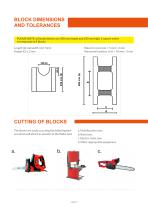
BLOCK DIMENSIONS AND TOLERANCES PLEASE NOTE: all Isotex blocks are 500 mm length and 250 mm high. 1 square meter corresponds to 8 blocks Holes for concrete + 5 mm/ -2 mm Horizontal lunettes (e-f) + 10 mm/ -3 mm Length (b) and width (d) ± 5mm Height (G) ± 2 mm CUTTING OF BLOCKS The blocks are easily cut using the following devices which will attach as utensils to the Widia tool: a. Multifunction saw; b. Band saw; c. Electric chain saw; d. Other appropriate equipment.
Open the catalog to page 8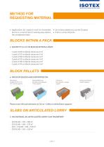
METHOD FOR REQUESTING MATERIAL • Applications for material must be forwarded by fax or e-mail at least 5 working days before the consignment date. • Un an articulated lorry carries 52 packs • A lorry carries 24 packs BLOCKS WITHIN A PACK • QUANTITY (in m²) OF BLOCKS WITHIN A PACK: - - - - - - 1 pack of 20 cm blocks measures 6 m² 1 pack of 25 cm blocks measures 5 m² 1 pack of 30 cm blocks measures 4 m² 1 pack of 33 cm blocks measures 4 m² 1 pack of 38 cm blocks measures 3 m² 1 pack of 44 cm blocks measures 3 m² BLOCK PALLETS • PACKS OF BLOCKS ARE SUPPORTED ON: PASS blocks (length 45-42-37-31 cm)...
Open the catalog to page 9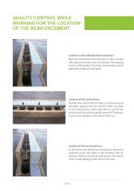
QUALITY CONTROL WHILE WORKING FOR THE LOCATION OF THE REINFORCEMENT Location of the individual horizontal bars: Rest the individual horizontal bars in the lunettes with spacers at every course of blocks. Overlapping must be 50% greater than that required by current applicable technical Standards. Location of the vertical bars: Position the vertical bar into the central position of the pillar, aligned with the vertical mark inscribed on the polystyrene, which operation is carried out at the same time as pouring the concrete. The above note on overlapping is also valid in this case. Location of...
Open the catalog to page 10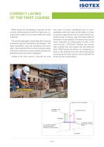
CORRECT LAYING OF THE FIRST COURSE While laying the foundations, insertion of the vertical reinforcement should be taken into account with a width of 25 cm (the width of the hole in blocks). The anchoring length conforming with technical standards must be indicated by the designer. The other possibility, once the foundation has been laid, is the insertion of this vertical reinforcement with resin on the first course of blocks laid (on the indication of the structure’s designer). Laying of the first course is carried out onto two layers of mortar positioned only in correspondence with the walls...
Open the catalog to page 11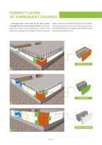
CORRECT LAYING OF SUBSEQUENT COURSES Arranged well at the level of the first course, starting from the corner blocks (UNI), we proceed with the laying of the subsequent courses completely dry having the foresight to keep the blocks tightly closed to avoid thermal and acoustic bridges. In this way, given the precision of the blocks, the use of insulating foams is avoided which ISOTEX does not recommend the use of. PASS Block
Open the catalog to page 12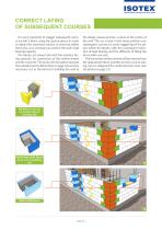
CORRECT LAYING OF SUBSEQUENT COURSES It is very important to stagger subsequent courses by half a block, using the special pieces in order to obtain the maximum volume to concrete within the forms, as is necessary to achieve the wall’s load bearing capacity. The blocks are always laid with the lunettes facing upwards, for connection of the reinforcement and the concrete. The parts with insulation towards the outside (see the illustration on page 15) and any necessary cut to the block for building the wall to the design measurements, is done at the centre of the wall. The cut is kept in the same...
Open the catalog to page 13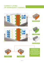
CORRECT LAYING OF SUBSEQUENT COURSES PASS Block CORNER BLOCKS: the cutting of the lunettes is performed for the connection of the reinforcement steel bars and concrete Course corners 1-3-5-7-9
Open the catalog to page 14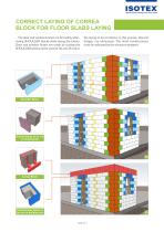
CORRECT LAYING OF CORREA BLOCK FOR FLOOR SLABS LAYING The door and window frames are formed by alternating SHOULDER blocks while laying the blocks. Door and window lintels are made by cutting the SHOULDER blocks at the yard (of 30 and 38 cm) or the laying of 44 cm blocks. In this manner, thermal bridges are eliminated. The lintel reinforcement must by indicated by the structure designer. Shoulder Block Half NS Block to be cut on building site Correa Block Half shoulder Block to be cut on building site
Open the catalog to page 15All ISOTEX SRL catalogs and technical brochures
 Isotex, intelligent technology
12 Pages

- Shuttering block
- Insulating shuttering block
- Wall shuttering block
- Industrial floor
- Noise barrier
- Wood fiber concrete formwork block
- Road noise barrier
- Structural floor with girder-slabs
- Concrete structural floor
- Insulated structural floor
- Concrete shuttering block
- Prefab noise barrier
- Home structural floor
- Prefab structural floor
- Insulating interjoist structural floor
- Concrete noise barrier
- Wooden noise barrier
- Flooring shuttering block
- Wooden structural floor
- Noise barrier for industrial applications