- Catalogs
- Intergraph
- SmartPlant P&ID Design Validation Product Sheet
SmartPlant P&ID Design Validation Product Sheet
1 /2Pages

SmartPlant P&ID Design Validation Product Sheet
1 /2Pages
Catalog excerpts
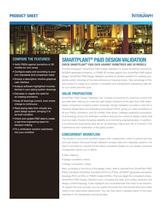
PRODUCT SHEET COMPARE THE FEATURES! • Verify P&IDs against isometrics or 3D models (or vice versa) SMARTPLANT® P&ID DESIGN VALIDATION CHECK SMARTPLANT® P&ID DATA AGAINST ISOMETRICS AND 3D MODELS Choose Intergraph® SmartPlant P&ID Design Validation to check SmartPlant Isometrics, • Configure easily and according to your own standards and comparison basis ISOGEN-generated isometrics, or PDMS 3D models against your SmartPlant P&ID logical • Employ a descriptive, intuitive graphical user interface piping system drawings at the data attribute and topology levels. Take advantage of this • Analyze software-highlighted inconsistencies in your piping system drawings design. SmartPlant P&ID Design Validation provides an iterative workflow for verifying your new product to create and maintain a consistent and standardized engineering data set for your entire plant life cycle. • Decrease or negate the need for re-creating isometrics VALUE PROPOSITION • Keep all drawings current, even where change is continuous accurate data, helping you make the right design decisions at the right time. With faster, • Read piping data from virtually any plant design system, bringing it to as-built condition resolving design flaws and preventing downstream errors, giving you data consistency in • Check and update P&ID data to create a real-time engineering basis for decision-making • Fit a verification solution seamlessly into your workflow SmartPlant P&ID Design Validation can increase productivity by ensuring current and easier comparison of piping system drawings, Design Validation provides a vital tool in all your P&IDs, isometrics, and 3D models. Rule-driven, intelligent graphical comparison of all drawings across the verification workflow reduces the number of design checks that must be made, thereby increasing reliability and minimizing engineering labor. In addition, a synchronized engineering data set for all drawings means less risk is involved in the maintenance and modification of the piping system. CONCURRENT WORKFLOW The solution’s concurrent workflow begins with configuration, which is performed only once per project. Because Design Validation accepts data from disparate systems, the data is converted to a neutral format before comparison (based on your design practices). Configuration allows you to define: • Data mapping • Design correlation criteria • Design comparison criteria Next, according to the focus of the design check, data is imported from SmartPlant P&ID (PIDs) and either SmartPlant Isometrics (PCFs or PODs), ISOGEN®-generated isometrics/ drawings (PCFs or IDFs), or PDMS models (DATAL). Then you begin the comparison phase. SmartPlant P&ID Design Validation auto-correlates the data, and verifies attributes and design content/topology. It also highlights any inconsistencies that need to be resolved. To support the work process, you can quickly document the mismatched items and make notes to the responsible department. You can then send a detailed report to the team members in the discipline(s) owning the data.
Open the catalog to page 1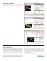
SMARTPLANT ENTERPRISE Intergraph’s SmartPlant Enterprise includes functionality similar to that of SmartPlant P&ID Design Validation. With SmartPlant Enterprise, in addition to comparison and validation tools, you can perform design with the P&ID inside the 3D model, which provides additional benefits. Figure 1: SmartPlant P&ID Design Validation allows navigation of the logical (2D) P&ID and provides graphical detailed views of the (3D) model data to examine the design content of related plant items. Figure 2: SmartPlant P&ID Design Validation shows any attribute inconsistencies between related...
Open the catalog to page 2All Intergraph catalogs and technical brochures
 GeoMedia®
14 Pages
 Leica CloudWorx? for PDS®
2 Pages
 SmartPlant® Cloud
2 Pages
 PV Elite
2 Pages
 CAESAR II
2 Pages
 PDS Ortho-Draw Product Sheet
2 Pages
 PDS Product Sheet
2 Pages
 SmartSketch Product Sheet
2 Pages
 SmartPlant 3D Product Sheet
2 Pages
 SmartMarine 3D Product Sheet
2 Pages


- Design software
- 3D software
- Industrial management software
- Analysis software
- Steel structure software
- 2D software
- Architecture software
- 2D/3D object library
- Computer-aided engineering software
- Electrical installation software
- Project management software
- Simulation software
- Mapping software
- Project simulation software
- Image editing software
- Sustainable design software