- Catalogs
- InSinkErator
- Foodservice Disposers
Foodservice Disposers

Foodservice Disposers
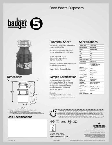
The InSinkErator Foodservice disposer is designed for commercial use and is certified by UL and CSA when installed with approved mounting adaptors and controls. Adhering to safety instructions is essential to prevent hazards.
- Ensure the drain line is clean before installation.
- Typical installation includes connections for a water shut-off valve, syphon breaker, solenoid valve, and control center.
- Required tools include screwdrivers, adjustable wrench, pipe wrench, wire nuts, and possibly plumbing putty and a hacksaw.
Standard and special mounting adaptors are available. Installation must comply with minimum distance requirements to prevent personal injury and property damage.
Proper plumbing connections are crucial to avoid damage. The drain line should have minimal horizontal runs and a proper fall. Connect the water supply to the cold water line only, using specified fittings.
Electrical installation must conform to local codes. The disposer must be grounded, and the motor voltage must match the electrical supply. Proper wiring is essential to avoid electrical shock and property damage.
Follow the operating instructions, including grinding tips and troubleshooting advice, to ensure efficient and safe operation.
The disposer is warranted against defects for one year from installation, covering parts and labor if serviced by an authorized center. The warranty excludes damage from improper installation or misuse.
- Ensure no foreign objects are in the grind chamber before starting.
- Start the disposer using the control switch; water will flow automatically.
- Feed food waste steadily into the disposer.
- Stop the disposer once all waste is flushed away.
- Run a steady stream of cold water during operation.
- Avoid overloading and ensure the disposer runs for three minutes after the final load.
Property Damage: Do not pre-load food waste to avoid strain and potential separation from the sink.
Fire Hazard: Keep flammable items away from the disposer.
Personal Injury: Only grind normal food waste. Ensure the baffle is installed and replace when worn. Avoid inserting fingers; use tools for object removal. Turn off power before clearing jams.
Electrical Shock: Disconnect power before servicing and ensure proper grounding.
Disposer won't start: Check water supply and electrical connections. Wait 30 seconds if the disconnect switch was activated.
Disposer won't start but water flows: Reset the overload protector or clear jams using a dejamming wrench.
Motor stops while grinding: Follow jam clearing steps and reset the overload protector.
Continuous water flow: Reinstall the water solenoid valve correctly.
Frequent overload trips: Avoid overloading with food waste.
Catalog excerpts

FOODSERVICE DISPOSER Installation Manual The Danger signal indicates an immediately hazardous situation which, if not avoided, will result in death or serious injury. The Warning signal alerts you to potential hazards or unsafe practices which, if not avoided, could result in severe personal injury or death. The Caution signal alerts you to hazards of unsafe practices which, if not avoided, may result in minor personal injury or property damage. Please be certain that the person who installs or uses this appliance carefully reads and understands the Safety Instructions contained in this manual. www.insinkerator.com/foodservice Part No. 13954 Rev.A
Open the catalog to page 1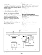
The InSinkErator Foodservice food waste disposer is UL® and CSA® Listed when installed in conjunction with InSinkErator mounting adaptors and controls (see Figure See Table 1 (page 4) for the approved disposer/ mounting adaptor combinations. See Table 3 (page 9) for the approved disposer/control combinations. Important - These installation instructions are for the benefit of the installing contractor. InSinkErator and/or InSinkErator Factory Authorized Service Centers do not make original installations. For technical information not covered in these instructions, contact the supplier, an InSinkErator...
Open the catalog to page 3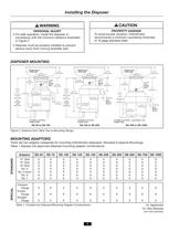
Installing the Disposer PROPERTY DAMAGE To avoid excess vibration, InSinkErator recommends a minimum countertop thickness of 16 gage stainless steel. PERSONAL INJURY • For safe operation, install the disposer in compliance with the minimum distance illustrated in Figure 2. • Disposer must be properly installed to prevent serious injury from moving shredder part. DISPOSER MOUNTING 6-1/2" (165.10 mm) 6-5/8" (168.28 mm) 6-1/2" (165.10 mm) 6-5/8" (168.28 mm) 2-3/4" (69.85 mm) 3-3/8" (85.73 mm) 24-1/4" TO 32-1/2" (615.95 mm TO 825.50 mm) 17" (431.80 mm) (WITH OPTIONAL LEGS INSTALLED) 13" (330.20 mm)...
Open the catalog to page 4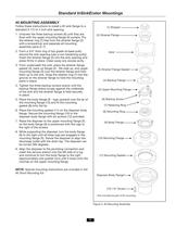
Standard InSinkErator Mountings #5 MOUNTING ASSEMBLY Follow these instructions to install a #5 sink flange to a standard 3-1/2 to 4 inch sink opening. (1) Stopper 1. Unscrew the three backup screws (6) until they are flush with the upper mounting flange (5) surface. Pry the retainer ring (7) free from the strainer flange (2) with a screwdriver and separate all mounting assembly parts (2-7). (2) Strainer Flange 2. Form a 3/4" thick ring of top grade oil base putty around the sink opening (use a non-hardening putty). Insert the strainer flange (2) into the sink opening and press firmly in place....
Open the catalog to page 5
Standard InSinkErator Mountings #6, #7, & SINK BOWL MOUNTING ASSEMBLIES 1. Place the mounting flange (1) over the existing collar 4. adaptor connection lip or sink bowl flange (this may require some force). 2. Push the mounting flange up out of the way and fit the groove in the mounting gasket (2) onto the connection lip. Make sure the gasket is fully seated 3. Push the mounting flange down over the mounting gasket, fitting the threaded mounting flange fasteners into the recesses in the top of the mounting gasket. Disposer Body Flange -► From the bottom, insert two screws through opposite sides...
Open the catalog to page 6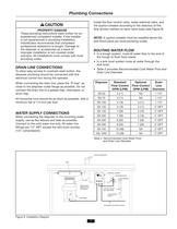
Plumbing Connections Install the flow control valve, water solenoid valve, and the syphon breaker according to the direction of the flow arrows marked on each valve body (see Figure 9). PROPERTY DAMAGE These plumbing instructions were written for an experienced competent installer. If the installer is not experienced in plumbing installation, InSinkErator recommends that competent professional assistance is sought. Damage to the disposer or accessories as a result of improper installation is not covered under warranty. All installations must comply with local plumbing codes. NOTE: A syphon breaker...
Open the catalog to page 7
Standard Motor Connection Wiring Diagrams NOTE: The diagrams below show standard motor connection wiring for a manual switch operation. For alternate controls, please refer to the control panel installation manual. 4 5 6 2 MOTOR LEAD WIRE# 1 2 5 11 1 7 L1 6 L2 L1 Figure 11. Incoming 208-230V Single Phase Line Power 12 4 MOTOR LEAD WIRE# 1 L1 7 2 L2 8 3 6 MOTOR LEAD WIRE# Figure 10. Incoming 115V Single Phase Line Power 10 5 4 7 3 L2 4 3 7 5 8 6 9 MOTOR LEAD WIRE# 9 1 Figure 12. Incoming 208-230V Three Phase Line Power 3 L1 L3 2 L2 10 11 12 L3 Figure 13. Incoming 460V Three Phase Line Power 8
Open the catalog to page 8
Electrical Connections ELECTRICAL CONNECTIONS To connect the disposer to the electricity: ELECTRICAL SHOCK • Turn off the electrical supply to the disposer before servicing. Test the circuit with a voltmeter or circuit tester to ensure the power is off. 1. Remove the screw in the center of the disposer terminal box. • Installation must conform to all local electrical codes. 3. Connect an electrical conduit connector to the hole in the bottom of the exposed wiring compartment. 2. Pull the terminal box out of the stainless steel trim shell. • All control centers and disposers must be grounded....
Open the catalog to page 9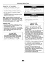
Operating Instructions OPERATING THE DISPOSER 1. Make sure there are no foreign objects in the disposer grind chamber. Do not pre-load the disposer with food waste prior to starting. FIRE HAZARD To minimize the possibility of fire, do not store flammable items near the disposer. Do not use or store gasoline or other flammable liquids near the disposer. 2. Push the start button on the control switch. The disposer will run and water will flow into the disposer. 3. Feed food waste into the disposer in a steady, continuous flow. 4. When all food waste is flushed away, push the stop button on the...
Open the catalog to page 10
Troubleshooting ELECTRICAL SHOCK Disconnect power before servicing. Troubleshooting for problems other than what is listed below should be performed by a qualified service person. Troubleshooting performed by untrained personnel could result in electrical shock or damage to the disposer. Disconnect power before servicing. PROBLEM Disposer will not start and water does not flow. POSSIBLE CAUSE SOLUTION • Turn on electrical supply. • Electrical disconnect switch has been reactivated and 30-second delay has not yet expired. • Wait 30 seconds and try starting again. • Disposer overload protector...
Open the catalog to page 11All InSinkErator catalogs and technical brochures
 SS SERIES
4 Pages
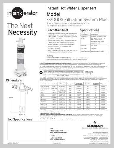
 HWT-F1000S
1 Page
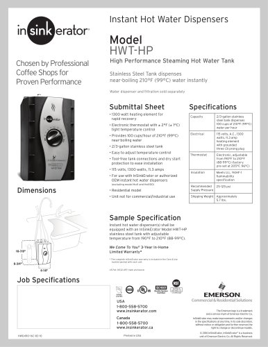 HWT-HP
1 Page
 F-2000
1 Page
 F-601R
1 Page
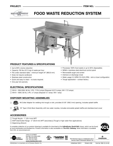
 WASTEXPRESS®
4 Pages
 HOT WATER DISPENSERS
2 Pages
 FOOD WASTE DISPOSERS
5 Pages
 Evolution Compact®
1 Page
 Evolution Excel®
1 Page
 SinkTop Switch?
2 Pages
 SST-FLTR
1 Page
 H770SS
1 Page
 H990-SS
1 Page
 H-Wave-SS
1 Page
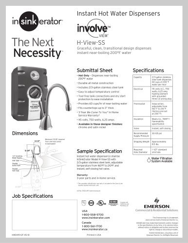 H-View-SS
1 Page
 HC-Wave-SS
1 Page
 HC-View-SS
1 Page
 F-GN1100
1 Page
 F-HC1100
1 Page
 F-GN2215
1 Page
 F-HC2215
1 Page
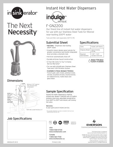 F-GN2200
1 Page
 F-HC2200
1 Page
 F-HC3300
1 Page
 F-H3300
1 Page
 SinkTop Switch
2 Pages
 Water Dispensing
20 Pages
 Badger 1
1 Page
 Badger 5
1 Page
 Badger 5XP
1 Page
 Pulper Systems Model WX-300
4 Pages
 Evolution Septic Assist
1 Page
 Evolution Cover Control
1 Page
 Evolution Essential
1 Page


Archived catalogs
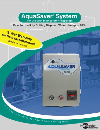 Aqua Saver Brochure
2 Pages
 Finish Matching Guide
2 Pages
 Evolution Excel
1 Page
 Evolution Compact
1 Page
 Hot & Cold Water Now
7 Pages


- Industrial tap
- Mixer faucet
- Indoor mixer tap
- Metal mixer tap
- 1-hole single-handle faucet
- Washbasin tap
- Countertop single-handle mixer tap
- Lavatory mixer tap
- Cold water tap
- Hot water tap
- Cold water mixer tap
- Stainless steel mixer tap
- Hot water mixer tap
- Kitchen mixer tap
- Cold water dispenser
- Industrial water filter
- Professional water filter
- Hot beverage water dispenser
- Commercial food waste disposer