HYDROTONE THERMAL LEVEL 3i
1 /1Page

HYDROTONE THERMAL LEVEL 3i
1 /1Page
Catalog excerpts
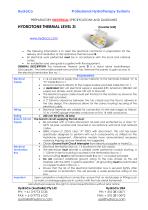
Professional Hydrotherapy Systems PREPARATORY ELECTRICAL SPECIFICATIONS AND GUIDELINES HYDROTONE THERMAL LEVEL 3i (Inverter Unit) The following information is to assist the electrical contractor in preparation for the delivery and installation of the Hydrotone Thermal Level 3i. • All electrical work performed must be in accordance with the local and national codes. • An installation and user guide is supplied with the equipment. GENERAL DESCRIPTION The Hydrotone Thermal Level 3i is a stand alone hydrotherapy tub/capsule. Two removable panels surround the tub. Remove the panels to gain access to the electrical termination Box no: 1. REQUIREMENTS Electrical • L1 & L2 electrical supply lines connect directly to the terminals marked “A” & Supply “N” inside Box no: 1 • Ground connects directly to the copper busbar provided inside Box no: 1. • A dedicated 240 volt electrical supply is required.(Nth American 208-240 volt supply two phases, each phase 120 volt to Ground) • The electrical supply cable should exit the floor in the location as shown in the floor plan provided. • A 2" (50mm) clearance between the tub chassis and the floor is allowed in the tubs design. The clearance allows for the correct routing/ securing of the electrical cable. Wiring • Electrical Terminals are suitable for connection of wire size ranges as follows: 10 to 14 AWG gauge stranded conductors or 8 to 14 solid conductors. Rating • 240 volt, 50/60 Hz, 20 Amp Branch Circuit The branch circuit supplying the tub must: Supply • Be provided with a mains disconnect all pole and protected by a class “A” GFCI all pole, located and mounted in accordance with local and national codes. • SBSG model LC 220-D class “A” GFCI with disconnect. This unit has been specifically designed to perform with such componentry as utilized on the Hydrotone equipment. Alternative models have demonstrated excessive nuisance tripping and are therefore not suggested. • Obtain Ground Fault Circuit Interrupter from electrical supplier or HydroCo. Electrical • Electrical termination Box no: 1 is located on the tub chassis. Termination • The electrician must provide a suitable water protective conduit bushing. A Box 1” (25mm) hole for bushing is located in the termination Box no: 1. • Ground wiring must be terminated inside Box no: 1 on busbar provided. • Do not connect additional ground wiring to the tubs chassis as this will interfere with the GFCI / systems operation. All grounding must be terminated on copper busbar in Box no: 1. • Ensure that the lid of the electrical termination box is secured tightly after completion of termination. This will provide a water-protective rating of the box. Important Upon completion of electrical connection, ensure that no metal pipes or fittings such as water or drainage pipes are in contact with the tubs metal framework. Manufacturer reserves the right to amend specifications without prior notice HydroCo (Australia) Pty Ltd PH: + 61 3 9773 5133 FAX: + 613 9773 6122 [email protected]
Open the catalog to page 1All HydroCo catalogs and technical brochures
 HYDRORAIN 7
1 Page
 HYDROWET 7
1 Page
 HYDROWOOD 7
1 Page
 PREPARATORY PLUMBING
1 Page
Archived catalogs
 Beyond
7 Pages
 Softime
12 Pages
 HydrotHerapy experience centers
36 Pages
 suspense
7 Pages
 suzi
suzi7 Pages
 product brochure
4 Pages
 hydro tan
2 Pages


- Industrial bath-tub
- Self-supporting bathtub
- Contemporary bath-tub
- Home bathtub
- Balneotherapy bathtub
- Industrial hammam
- Red bathtub
- Commercial hammam
- Bathtub with light
- Home hammam
- Ceramic bathtub
- Commercial relaxation water bed
- Water massage table
- Metal shower
- Shower with hinged door
- Vichy shower
- Commercial Vichy shower
- Spa capsule
- Horizontal Vichy shower
- Prefab hammam