
Catalog excerpts

Technical information Installation instructions BioLyt (8-36) Wood pellet boiler Hoval products must be installed and commissioned by specialists. These instructions are intended for the specialist. Electrical installation must be performed by a licensed electrician.
Open the catalog to page 1
Important notes Technical information
Open the catalog to page 2
Table of contents 5. Commissioning
Open the catalog to page 3
Important notes Important notes On delivery Carry out an immediate visual inspection of the boiler on receipt of the delivery. If damage is ascertained, immediately take the steps specified in the delivery contract. The respective risk carrier bears the cost of repairs. Regulations, official approvals The standards and directives listed under point 1.7 must be observed when installing and operating the system. Tool: Shows the tools required to perform the work described below. The warranty does not cover defects as a result of: • Non-observance of these instructions • Non-observance of the...
Open the catalog to page 4
Important notes 1.7 Standards and directives 1.7.1 Germany § EnEV 1.BimSchV TRD 721 TRD 414 DIN 4702 Part 4 DIN 4807 DIN 4753 Part 1 DIN 1988 Part 2 VDI 2035 DIN V 18160 DIN 4795 Local building regulations FeuV Energy conservation ordinance in the current version. 1st Act for the implementation of the applicable Federal Immission Protection Act, in the current version. Safety valves for steam boilers of group II (also applies to heat generators with safety temperatures below 100 °C) Wood-fired combustion systems on steam boilers Boilers, general; Boilers for wood and other biomass fuels...
Open the catalog to page 5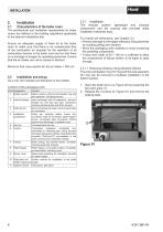
Characteristics of the boiler room The architectural and ventilation requirements for boiler rooms are defined in the building regulations applicable to the relevant installation site. Ensure an adequate supply of fresh air to the boiler room to make sure that there is an unobstructed flow of the combustion air required for the operation of all combustion devices in the boiler room and so that there is no shortage of oxygen for operating personnel. Ensure that the air intake can not be closed or blocked. Minimum free cross-section for the air intake = 200 cm2. As a rule, the modules are...
Open the catalog to page 6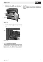
Installation 3. Using both hands, pull the post-combustion ring (3, Figure 02) horizontally out of the bottom section. Observe the minimum wall clearances (see Chapter 3.4 and 3.5). If required, the boiler door can also be attached on the left. Figure 02 4. Lift the dust separator (4, Figure 03) straight upwards, guide it towards the rear over the retaining bracket and via the post-combustion ring rail towards the outside. Figure 03 2.2.1.2 Fitting refractory lining elements The elements are fitted by following the instructions above in reverse order. Pay attention to the side nipple on the...
Open the catalog to page 7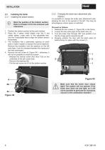
Installation 2.3 Installing the boiler 2.3.1 Installing the bottom section Mark the position of the bottom section. Refer to Chapter 3.5 for the minimum wall clearances. 1. Position the bottom section at the point marked. 2. Place the 4 green metal plates over the 4 red rubber plates; under each of the adjustable feet. Use the 4 adjustable feet to align the bottom section horizontally. 3. The insulation has a perforated opening on each side to make it easier to expose the burner aperture. Remove the insulation over the aperture on the left side (later, it can be clamped between the casing...
Open the catalog to page 8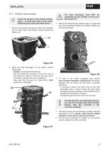
Installation 2.3.3 Fitting the heat exchanger Check the position of the bottom section again – It could have been moved while performing the steps described above! 1. Remove the tension springs and bend the insulation mat (1, Figure 06) on the bottom section towards the boiler door. The heat exchanger must NOT be suspended by the handles on the cover (2b, Figure 07). 3. Remove the three thread protection caps (3, Figure 08) from the connections between the bottom section and the heat exchanger. Figure 06 2. Place the heat exchanger on the bottom section (Figure 08). -- Caution: It weighs...
Open the catalog to page 9
Installation 7. Fold the insulation mat back into place and secure with the tension springs. The connection between the bottom section and the heat exchanger must seal tightly! If possible, now pressure-test the bottom section with the heat exchanger, checking for leakage (mains water pressure is sufficient). If a leak is not detected until after the electrical connections and the casing have been installed, it is much more difficult to remedy the fault. 1. Remove the ash wiper ring (1, Figure 09) from the burner plate (1a) to facilitate insertion of the burner (1c). 2. To do this, turn the...
Open the catalog to page 10
Installation 4. Turn the two hammer-head bolts on the burner to vertical position. Figure 11 5. Lift the prepared burner up obliquely and guide it carefully into the bottom section. Fit the burner onto the two pins (5, Figure 12) on the bottom section. Never turn the hammer-head bolts anticlockwise - turning them just a short distance in anti-clockwise direction will release them from their anchoring in the bottom section! 8. Check that the burner is tightly seated on the bottom section. 9. To make it easier to fit the ash wiper ring, release screw (9, Figure 13) and remove the ash wiper...
Open the catalog to page 11
Installation 2.3.5 Fitting the control, routing probes and sensors 1. Remove the transport locking device (1, Detail A) from the heating surface motor by releasing the nut (1a) and remove screw with locking nut (1b). Reattach the heating surface motor by replacing the M8 nut and locking ring. 2. Fit the automatic firing device: -- Insert the four M5x50 screws (2, Figure 14) into the support plate (2a) from below. -- Place the support plate on the bracket on the boiler (2b, Detail A) and fix it in position with two M6x12 screws (2c) each on the left and right. -- Turn the four M5x12 screws...
Open the catalog to page 12
Installation 2.3.6 Fitting the casing and the pellet hopper 1. The controller box (1, Figure 15) was already premounted in Chapter 2.3.5. 2. Holding it at a slight angle, mount the lower back panel (2) on the screws of the casing side panel. 3. Mount the middle (3a) and upper back panel (3b) on the casing side panel. 4. Fit the pellet hopper using screws: -- First, turn the four M8x25 screws with collar (in the pellet hopper screw set included with the delivery) into the brackets (4) on the boiler (spacing approx. 1 cm). -- BioLyt (8,13) only: Remove the pellet hopper lid (4b, Figure 15) by...
Open the catalog to page 14All Hoval Italia catalogs and technical brochures
-
 Spare parts list
10 Pages
-
 Hoval HomeVent®
1 Pages
-
 Gotthard
4 Pages
-
 PressVal Intermediate
2 Pages
-
 Ceramic Filter
8 Pages
-
 CT-plus
4 Pages
-
 Max-3
Max-38 Pages
-
 TransTherm
12 Pages
-
 RoofVent Design Handbook
280 Pages
-
 UltraSol and UltraSol eco
115 Pages
-
 Plate heat exchangers
40 Pages
-
 ServeLine
8 Pages
-
 Modul-plus
4 Pages
-
 PowerBloc CHP
8 Pages
-
 Product overview
2 Pages
-
 BioLyt Wood Pellet Boiler
12 Pages
-
 UltraGas® Condensing Gas Boiler
12 Pages
-
 SR-plus brochure
8 Pages


Archived catalogs
-
 BioLyt. 10-26
10 Pages
-
 AgroLyt
14 Pages
-
 TopGas 30-60
9 Pages
-
 Cosmo
Cosmo10 Pages
-
 Uno3-cosmo TCAF
7 Pages
-
 MultiJet®
22 Pages