Catalog excerpts

HE360A,B Powered Flow-Through Humidifier INSTALLATION GUIDE/OWNER’S MANUAL
Open the catalog to page 1
HE360A,B POWERED FLOW-THROUGH HUMIDIFIER
Open the catalog to page 2
HE360A,B POWERED FLOW-THROUGH HUMIDIFIER WELCOME To the comfortable world of humidified air. When you use your Honeywell humidifier, notice that your skin is not as dry, and that your scratchy throat and irritated nasal passages that aggravate allergies and asthma are steadily improving. You have also taken the first step in reducing the zapping you create when you walk on your carpet and then touch your TV, computer, metal door knob or your pet. Your furniture and woodwork are also benefitting from the difference that humidified air makes. Congratulations! You have just made a great...
Open the catalog to page 3
HE360A,B POWERED FLOW-THROUGH HUMIDIFIER Installation Accessories (Available in Installation Kit 32005847-00) Table 1. Required Accessories
Open the catalog to page 4
HE360A,B POWERED FLOW-THROUGH HUMIDIFIER Required Tools Tools required for installation include: • • • • • • • Tin snips. Screwdriver. Adjustable or open-end wrench. Battery-powered Drill, punch or awl. Level. Work Gloves (preferably cut-resistant). Safety Glasses.
Open the catalog to page 5
HE360A,B POWERED FLOW-THROUGH HUMIDIFIER INSTALLATION Preparing for the Installation Be sure to identify all the required (Table 1) accessories (included) and make sure the appropriate tools are available before beginning the installation. Hazardous Voltage Can cause personal injury or equipment damage. Do not cut or drill into any air conditioning or electrical accessory. Sharp Edges Installation Hazard. Can cause personal injury. Wear gloves and safety glasses. Turn off power to the air handing system at the circuit breaker. Draw a level line on the plenum in the location chosen for the...
Open the catalog to page 6
HE360A,B POWERED FLOW-THROUGH HUMIDIFIER • Select a location that cannot damage the air conditioner A-coil during installation. • Do not locate the humidifier on the furnace body. • Allow adequate clearance in front of and above the humidifier so you can easily remove the cover to perform routine maintenance. — Mount the humidifier at least 3 in. (78 mm) above the furnace body to allow adequate space for the solenoid valve and drain line. — Mount the humidifier in a conditioned space to prevent freezing. Selecting Water Supply Location • Use either hard or soft water in the humidifier and...
Open the catalog to page 7
Locating Closest 120V Electrical Outlet • Select location with access to an outlet. If not available, contact an electrician to have one installed. • Make sure that the humidifier cord is adequate to reach from the humidifier to the outlet. • Make sure that the 20 ft (6.2m) of thermostat wire is adequate to reach from the humidifier solenoid, to the sail switch, to the humidistat. Installing the Humidifier A WARNING Hazardous Voltage Can cause personal injury or equipment damage. Do not cut or drill into any air conditioning or electrical accessory. A CAUTION Sharp Edges Installation...
Open the catalog to page 8
Make sure the humidifier housing is level, then position it in the opening so the plastic tabs are in place on the lower sheet metal edge of the opening. Use pliers, as necessary, to flatten cut edges. See Fig. 4. Push in securing clips until completely seated. Drill holes and install the three sheet metal screws on the top of the humidifier housing. Secure the housing with the three remaining screws. LEVEL SHEET METAL SCREWS (4) DRAIN TUBING Fig. 4. Installing humidifier on duct. 5. Reinstall the humidifier pad assembly in the humidifier housing. IMPORTANT Be sure to reconnect the water...
Open the catalog to page 9
HE360A,B POWERED FLOW-THROUGH HUMIDIFIER Connecting the Plumbing Use hot or cold water and either hard or softened water in the humidifier. 1. Chemical Hazard. Can cause personal injury or equipment damage. Do not use any line connected to an air conditioner. Do not use gas line. Use the self-piercing saddle valve (included) to tap into the water supply line at the location selected. See Fig. 5. If tapping into galvanized pipe, drain line and pre-drill 3/17 in. tap for saddle valve. The saddle valve is not designed to regulate water flow. The valve is either open or closed. IMPORTANT To...
Open the catalog to page 10
HE360A,B POWERED FLOW-THROUGH HUMIDIFIER NOTE: To prevent leaking, use plastic (Delrin) sleeve rings with plastic tubing. Use copper sleeve rings only with copper tubing. d. Insert the tubing into the solenoid valve fitting and support the valve while tightening the compression nut. NOTE: Do not over-tighten the compression nut. Moderate tightness prevents leaking. e. Repeat steps a. through d. for solenoid valve fitting. f. Secure tubing with clamps provided. BRASS COMPRESSION NUT PLASTIC COMPRESSION RING BRASS INSERT Fig. 6. Installing feed tubing. 4. Connect a 1/2 in. (13 mm) drain tube...
Open the catalog to page 11
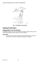
HE360A,B POWERED FLOW-THROUGH HUMIDIFIER Fig. 7. Installing the drain tubing. Installing the Sail Switch Adapting Switch to Air Flow Direction The S688A Sail Switch has two counterbalancing springs in place as shown in Fig 8. These springs offset the effect of gravity for air flow direction. IMPORTANT: Do not use the sail switch with both springs attached. Be sure to select air flow direction and remove spring(s) not required for installation.
Open the catalog to page 12
HE360A,B POWERED FLOW-THROUGH HUMIDIFIER Fig. 8. Adapting sail switch to air flow direction or mounting position. • Vertical downward air flow: Leave the spring in place that is attached to the bracket marked Down. Remove the spring that is attached to the bracket marked Up. • Vertical upward air flow: Leave the spring in place that is attached to the bracket marked Up. Remove the spring that is attached to the bracket marked Down. • Horizontal air flow: Remove both springs. 1. Mount the template (provided with the sail switch) at the desired location. NOTE: Be sure the arrow (indicating...
Open the catalog to page 13
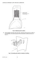
HE360A,B POWERED FLOW-THROUGH HUMIDIFIER – LOOSEN SETSCREW – INSERT SAIL CORD – TUCK CORD INTO TAB SLOTS – TIGHTEN SETSCREW Fig. 9. Attaching sail to switch. Press together the sides of the wire loop. Insert the sail into the duct. (When in the Off position, the sail should point into the direction of airflow as shown in Fig.10.) Fig. 10. Inserting sail switch in direction of airflow.
Open the catalog to page 14All Honeywell catalogs and technical brochures
-
T10 Pro Smart Thermostat
4 Pages
-
VisionPRO® 8000 Intelligent
2 Pages
-
VisionPRO® 8000 Smart
2 Pages
-
DR90A3000
2 Pages
-
TrueEASE™ Humidification System
72 Pages
-
Honeywell Media Air Cleaners
20 Pages
-
C7189R
20 Pages
-
DR120A3000
2 Pages
-
DR65A3000
2 Pages
-
Wi-Fi® Thermostat 9000
92 Pages
-
RTH9585
76 Pages
-
MN12CES / MN10CESWW
20 Pages
-
AquaReset Brochure
2 Pages


