Catalog excerpts

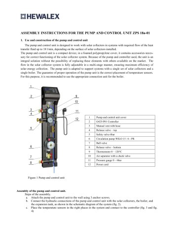
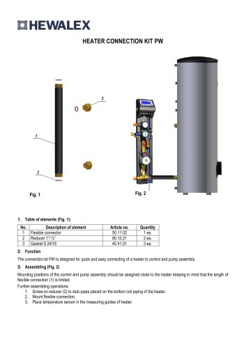
ASSEMBLY INSTRUCTIONS FOR THE PUMP AND CONTROL UNIT ZPS 18a-01 1. Use and construction of the pump and control unit The pump and control unit is designed to work with solar collectors in systems with required flow of the heat transfer fluid up to 18 l/min, depending on the surface of solar collectors installed. The pump and control unit is a compact device, in a foamed polypropylene cover, it contains accessories necessary for correct functioning of the solar collector system. Because of the pump and controller used, the unit is an integral solution without the possibility of replacing these elements with others available on the market. The flow in the solar collector system is fully adjustable in a multi-stage manner, ensuring maximum efficiency of solar energy collection. The pump unit is adapted to support systems with a single set of solar collectors and a single boiler. The guarantee of proper operation of the pump unit is the correct placement of temperature sensors. For this purpose, it is recommended to use the appropriate connection unit for the boiler. 12 Figure 1 Pump and control unit Assembly of the pump and control unit. Steps of the assembly. a. Attach the pump and control unit to the wall using 3 anchor screws. b. Connect the hydraulic connections of the pump and control unit with the solar collectors, the boiler, and the expansion tank, as shown in the schematic diagram of the system (fig. 2). c. Place the temperature sensors in the right places in the system and connect to the controller (fig. 3 and fig. 4)
Open the catalog to page 1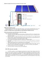
Diagrams of pump and control unit connections in the solar system T1 Hot water Supply from central heating boiler Circulation T2 Return to central heating boiler Filling and starting the system. The system should be filled with a heat transfer fluid, which is a water solution of propylene glycol, with a crystallization temperature of –25°C with an addition of an inhibitor pack, protecting the system from corrosion. Attention!!! The fluid with the freezing temperature stated should not be diluted with water. Fill the system with heat transfer fluid using a turbine-driven pump. Steps of the...
Open the catalog to page 2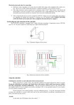
Electrical system and rules for connecting. Electrical system (regardless of its type) must be ended with a plug socket equipped with a safety contact. The use of a socket without the protective conductor terminal is a risk of electric shock!!! The crimp connectors used are approved for continuous load of 16A!!! They feature a fine thread and special plates to prevent crossing of wires, and therefore only a slight tightening of the cable creates a maximally good contact and the use of greater force may lead to breaking the thread. After connecting the device to power, dangerous 230VAC...
Open the catalog to page 3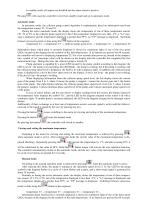
In standby mode, all outputs are disabled and the alarm sound is inactive. Pressing will cause the controller to exit from standby mode and go to automatic mode. Automatic mode. In automatic mode, the collector pump control algorithm is implemented, based on information read from the temperature sensors T1, T2 and T3. During the active automatic mode, the display shows the temperature of one of three temperature sensors (T1, T2 or T3) or the collector pump speed level, but if the temperature displayed is less than -9°C, a "Lo" message is displayed, and the temperature displayed is greater...
Open the catalog to page 4
the controller will revert to displaying temperature T2. For a few seconds after power up, instead of the temperature, symbol of 'un' (uncertain value) will be shown on the display until the controller has completed the first measurement loop. Information about the failure of one of the sensors is displayed the same way as in automatic mode. The controller will return to automatic mode automatically after 10 minutes after activating the manual mode, or after pressing the controller will switch to standby. Protection To protect the system from high temperature, circulation of steam bubbles...
Open the catalog to page 5All HEWALEX Solar Collectors catalogs and technical brochures
-
G-422-P03
18 Pages
-
INTEGRA Universal heaters
2 Pages
-
HEATER CONNECTION KIT PW
1 Pages

