Catalog excerpts
USER’S MANUAL OF AN INDEPENDENT REGULATION BLOCK Controller of a solar collector system
Open the catalog to page 1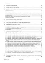
Tap water heating – controlling P solar pump, circulation pump and pump of K external device (solid-fuel burner) – scheme no. 6 . 12
Open the catalog to page 2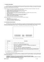
G422-P03 Controller is a device designed and produced to be used with solar collector installations. This product has been created on the basis of a faultless modern microchip technology. The controller has a modern look and is very easy to use, thanks to its user panel which features a simple keyboard and an LCD screen. A powerful feature of the controller is its extended packet of basic options, which significantly increases its functionality. These include: • A selection of many different installation configurations (schemes) • Installation diagrams with animated symbols representing...
Open the catalog to page 3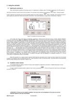
3. Using the controller 3.1 Switching the controller on After connecting the controller to the power source, it is operating in a standby mode. The diode is solid green, the LCD screen is half-lit and it shows the current version of the controller. The controller can be switched on by pressing button. During its regular mode of operation the controller can be put into standby mode at any time by pressing . When in standby, all the outputs and sound alarm signals are switched off. When the controller is switched on, the screen displays an image similar to that shown in Figure 2. Figure 2. An...
Open the catalog to page 4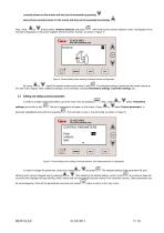
currently shown on the screen and they can be accessed by pressing . ▲ indicates that more options are available above those currently shown on the screen and they can be accessed by pressing Next, using or buttons select Scheme selection and press . After entering the scheme selection menu, the diagram of the scheme is displayed on the screen together with the scheme number, as shown in Figure 4. Figure 4. Screen display when selecting a desired scheme configuration. By using or select the desired scheme and confirm it with . The selected setting is saved and the screen returns to the main...
Open the catalog to page 5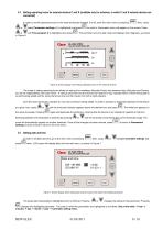
3.4 Setting operating hours for external devices C and K (available only for schemes, in which C and K external devices are connected) In order to set the operating hours for the external devices denoted C or K, enter the main menu by pressing or select Parameters settings (it is highlighted) and press or until Time program C is highlighted and press in Figure 6. . Next, using to confirm. Parameters menu will appear on the screen. Press . The controller turns into edit mode and displays hour diagrams, as shown Figure 6. Screen display when setting operating hours for the external devices....
Open the catalog to page 6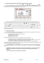
3.6 Manual control of external devices connected to the controller (scheme 8 as an example). In order to switch external devices on manual control press and using or highlight Manual Control. Press . On the screen the current installation scheme will be displayed. On the right-hand side the letters representing connected external devices are shown, together with their corresponding operation status, as shown in Figure 8. Figure 8. Screen display when setting the manual control on external devices. Depending on the selected installation scheme, the controller controls from one to three...
Open the catalog to page 7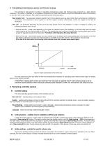
5. Calculating instantaneous power and thermal energy The controller is featured with a function of calculating instantaneous power and thermal energy produced by a solar collector installation. The function is available for all installation schemes with a single solar collector pump P and temperature sensor T3 connected on the return to the solar collectors. Also, additional parameters need to be set properly: Heat transfer fluid – the parameter related to specific heat of the substance used as heat transfer fluid and defines its solidification temperature. The temperature value is given...
Open the catalog to page 9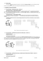
6.4 Default settings This function restores default settings of the controller. It can be found in Parameters settings menu, as the last listing. Entering that option and pressing will replace current settings with the default settings and saves it in the controller memory. 7. Installation schemes description 7.1 Tap water heating – controlling solar pump – scheme no.1 Controlling solar pump – P speed regulation disabled. Solar collector pump P will be switched on if temperature in collectors, measured by sensor T1, is greater than that measured by sensor T2 (in the bottom of the water...
Open the catalog to page 10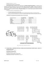
Analogical to scheme no. 2 - see 7.2 Controlling external device K to heat tap water external device K (boiler) is switched on only in periods preset in Parameters settings/Time program K. It is switched on when temperature, measured by sensor T4 (on the top of the water heater) is lower than that preset for T4max. The boiler will be switched off when temperature measured by T4 sensor increases above the value T4max. Additionally, the operation of the boiler can be set to be dependent on solar collectors instantaneous power output. In such case, the device will be switched off if the...
Open the catalog to page 11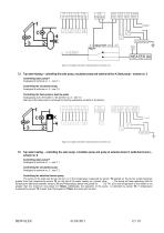
Figure 13. Graphic and electric representation of scheme no.4. 7.5 Tap water heating – controlling the solar pump, circulation pump and external device K (heat pump) – scheme no. 5 Controlling solar pump P Analogical to scheme no. 1 – see 7.1 Controlling the circulation pump Analogical to scheme no. 2 – see 7.2 Controlling the heat pump to heat tap water Analogously as for the boiler in the scheme no. 3 – see 7.3 Start-up of the heat pump is achieved by shorting respective contacts of the device. Figure 14. Graphic and electric representation of scheme no.5. 7.6 Tap water heating –...
Open the catalog to page 12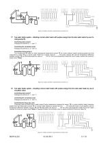
Figure 15. Graphic and electric representation of scheme no.6. 7.7 Two water heater system – reheating a burner water heater with surplus energy from the solar water heater by use of a mixing pump (K) Controlling solar pump P Analogical to scheme no. 1 – see 7.1 Controlling the circulation pump Analogical to scheme no. 2 – see 7.2 Controlling mixing pump K The mixing pump will switch on when temperature measured by sensor T2 (in a solar collector heater) becomes greater than that measured by sensor T4 (in a burner water heater) by a preset value for ΔT2. The pump remains ON until the...
Open the catalog to page 13All HEWALEX Solar Collectors catalogs and technical brochures
-
HEWALEX
5 Pages
-
INTEGRA Universal heaters
2 Pages
-
HEATER CONNECTION KIT PW
1 Pages


