
- Catalogs
- HEWALEX Solar Collectors
- ASSEMBLY INSTRUCTIONS FOR THE PUMP AND CONTROL UNIT 18e-01


ASSEMBLY INSTRUCTIONS FOR THE PUMP AND CONTROL UNIT 18e-01

ASSEMBLY INSTRUCTIONS FOR THE PUMP AND CONTROL UNIT 18e-01
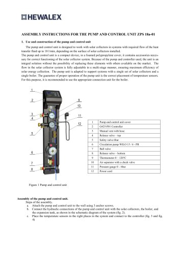
The pump and control unit is designed for use with solar collectors, allowing for maximum flow rates of up to 18 l/min. It is housed in a foamed polypropylene cover and includes necessary accessories for solar installation functionality. Key components include a G422 controller with temperature sensors, a circulating pump, and various valves and meters.
The document provides a schematic diagram for connecting the pump and control unit to solar collectors, a boiler, and an expansion tank.
- Mount the unit using anchor screws as per the specified spacing.
- Connect hydraulic connections according to the schematic diagram.
- Install temperature sensors and connect them to the controller.
- Fill the system with a specified heat transfer fluid, ensuring no dilution with water.
- Use a rotary pump to fill and de-aerate the system, achieving a system overpressure of 2.5 bar.
- Set the required flow rate based on the number of solar collectors.
The G422 controller manages circulation pumps and other devices in solar installations. It features an LCD screen and buttons for operation, displaying current installation schemes, temperatures, and power output. It includes parameters for solar collector type, temperature differences for pump operation, and overheat and freeze protection settings.
The controller can indicate errors such as temperature sensor failures and insufficient flow. It provides alarms and messages to guide troubleshooting, including steps to restart the pump if necessary.
Catalog excerpts

1. Use and construction of the pump and control unit Pump and control unit is used to cooperate with solar collectors in an installation with a required heat transfer fluid. Maximum flow rates of up to 18 l/min can be set, depending on the area of the mounted solar collectors. The pump and control unit is compacted in a foamed polypropylene cover and it contains accessories necessary for correct functioning of the solar installation. Construction of the pump and control unit is presented in Figure 1 below. Spacing of 010 openings for attaching the unit 81mm 23 mm Fig. 2. Diagram of spacing between 010 openings necessary for attaching the pump control unit
Open the catalog to page 1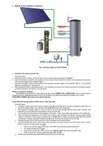
2. Diagram of solar installation connections Fig. 3. Schematic diagram of solar installation 3. Assembly of the pump and control unit. Consecutive steps. a. Attach the pump and control unit to the wall using 3 anchor screws in spacing as presented in Figure 2. b. Connect the hydraulic connections of the pump and control unit with the solar collectors, the boiler, and the expansion tank, as shown in the schematic diagram of the installation (Fig. 3). c. Cold water connection should be done according to the presented schematic diagram of the installation (Fig. 3), or the schematic diagram of the...
Open the catalog to page 2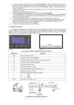
h. In case of a reduction or interruption of the flow (message “flow insufficient” - confirm with the OK button) turn counter clockwise the circulation pump main screw (11) and let out the air blocking the pump. Continue till full deaeration of the system. If, after 5 minutes, the flow is still insufficient, the controller will issue a “Pump blocked...” message - in order to switch the pump on again, press OK button. i. In case the pressure measured by the pressure gage (12) is below 1.5 bar, fill in the system to reach required system overpressure of p = 2.5 bar. j. Disconnect supply and overflow...
Open the catalog to page 3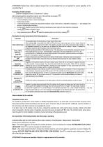
ATTENTION!!! Dashed lines refer to optional sensors than can be installed but are not required for correct operation of the controller (Fig. 1). Description of G422 controller Controller is equipped with an LCD screen and 7 buttons. After connecting electric connections correctly, turn on the controller by pressing . In normal operation, the controller's screen displays: • Current installation scheme number and diagram, • Current date and time, • Current temperatures in respective measurement locations (a lack of the sensor is indicated by displaying - - -, and damage of the sensor by displaying...
Open the catalog to page 4All HEWALEX Solar Collectors catalogs and technical brochures
 G-422-P03
18 Pages
 HEWALEX
5 Pages
 INTEGRA Universal heaters
2 Pages
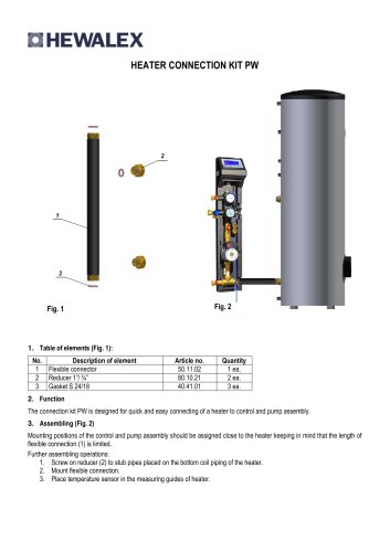 HEATER CONNECTION KIT PW
1 Page


- Industrial heat pump
- Residential heat pump
- Air source heat pump
- Industrial solar panel
- Outdoor heat pump
- Mechanical ventilation unit
- Commercial heat pump
- Thermal solar collector
- Mounting system
- Flat thermal solar collector
- Photovoltaic panel mounting system
- Water heating thermal solar collector
- Thermal solar collector with frame
- Solar mounting system
- Heating thermal solar collector
- Roof thermal solar collector
- Thermal solar collector with aluminum frame
- On-roof mounting system
- Integrated mounting system
- Thermal solar collector with anti-reflective glass