HFB - Airflow Management Damper
1 /17Pages

HFB - Airflow Management Damper
1 /17Pages
Catalog excerpts
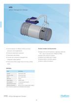
HFB Airflow Management Damper Product models and Accessories • Control damper for different airflow and duct pressure control applications • Model with shut-off operation; tightness fulfils EN • Pressure-independent operation 1751, class 4 requirements (HFB/G & HFB/I) • Galvanised steel design • Model with external insulation • Circular duct connection equipped with • Several sound attenuator models integrated rubber gaskets • Several airflow controller options • Factory-set airflow range limits (min./max. airflow • Electric reheat coil options MATERIAL PART Galvanised steel Damper blade Galvanised steel Zinc coated steel Blade gasket EPDM rubber Duct gaskets Measurement probe External insulation Mineral wool (models HFB/I, HFB/J) Duct connection gaskets are vulcanised to the casing. HFB - Airflow Management Damper 60
Open the catalog to page 1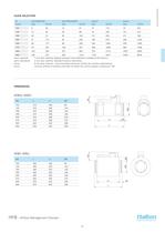
qmin (special) qmin (standard) qmax qnom 1 m/s duct velocity. Special actuator and calibration needed at the factory. 2 m/s duct velocity. Standard factory calibration 6 m/s duct velocity - recommended maximum airflow for comfort applications nominal airflow of airflow controller at which the control signal is maximum 10V HFB/I, HFB/J HFB/G, HFB/H HFB - Airflow Management Damper 61 QUICK SELECTION
Open the catalog to page 2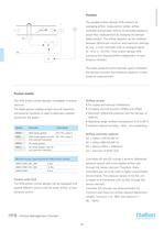
The variable airflow damper HFB contains an averaging airflow measurement probe, airflow M controller and actuator. Airflow is controlled based on actual flow measurement by changing the damper blade position. The airflow setpoint can be modified between factory-set minimum and maximum settings by, e.g., a room controller with an analogue signal (0...10 or 2...10 VDC). Flow control damper HFB maintains the required airflow independent of duct TC pressure variation. The static pressure control damper option maintains the desired constant duct pressure based on a static pressure measurement. Product...
Open the catalog to page 3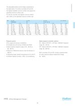
The adjustable airflow control range is presented in the table below. For airflow controllers EE and EG, the highest available minimum airflow rate equals the specified maximum airflow rate. For the ED controller, the highest minimum airflow rate is 80% of the specified maximum airflow rate. NS Pressure control Static pressure controller options: • For supply and exhaust installations ES = Belimo VRP-STP + VFP-100 + NM24A-V (setpoint • Complete shut-off function (HFB/G and HFB/I) • Static pressure setpoint range of 30...100 Pa or ER = Belimo VRP-STP + VFP-300 + NM24A-V (setpoint • Maximum differential...
Open the catalog to page 4
Sound attenuators are available with optional outlet diameters with mineral wool (MW) or polyester ACCESS PANEL fibre (PEF) insulation materials and with 600 mm and 1000 mm lenghts. Optionally the attenuator can be equipped with an access panel for cleaning and inspection purposes. Attenuator without access panel Attenuator with access panel The connection (D1) is female type for direct connection to the HFB airflow control damper. The duct connection (D2) is male type and either damper size or one size larger. Technical information is based on bigger of the duct connections (D2). Attenuator...
Open the catalog to page 5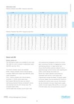
Attenuation data Material, Mineral wool (MW), frequency band (Hz) L = 600 Material, Polyester fibre (PEF), frequency band (Hz) L = 600 Reheat coils (RH) Electric reheat coil The HFB electric reheat coil is available for duct sizes with potential-free changeover contact for remote 100...400 mm, and it is always a single-phase heater alarm monitoring. The alarm is triggered by manual overheating protection or heater power loss. Ensure that the airflow velocity is above 2 m/s to Two electric reheater options are available: guarantee proper control function when selecting the • RM = Electric reheater...
Open the catalog to page 6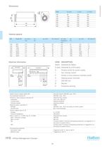
Electrical information CODE DESCRIPTION Halton Delivered by Halton 3rd party Delivered by a third party S All-pole switch for power supply Airflow or duct pressure interlock switch Heating power controller Protective earthing Heater power supply switch (S) Airflow or duct pressure interlock (P) - Indication - Contact open - Contact closed Potential-free contact 10 V, max. 500 mA Heating disabled Heating enabled Heating power controller H - Voltage - On/off cycle PWM 230 VAC, max. 16 A, according to heater power 60 s recommended Control signal input 9, 10 - Voltage - Internal impedance Alarm output...
Open the catalog to page 7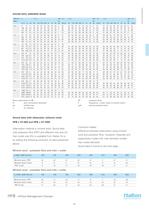
SOUND DATA, AIRBORNE NOISE Room attenuation 4 dB dP pressure drop D duct connection diameter F frequency, ( mean value of octave band ) qv airflow rate LpA sound pressure level Sound data with attenuator, airborne noise Attenuation material is mineral wool. Sound data with polyester fibre (PEF) and different inlet size (IL) than outlet size (OL) is available from Halton hit or by adding the following correction to data presented Mineral wool - polyester fibre and inlet < outlet Correction tables: Difference between attenuation using mineral wool and polyester fibre. Insulation materials and respectively...
Open the catalog to page 8
SOUND DATA WITH ATTENUATOR, AIRBORNE NOISE, HFB + H1-600 -Airflow Management Damper
Open the catalog to page 9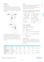
Safety distances The airflow control damper is installed taking into account the required safety distances. Install the unit into ductwork in such a way that the air flow direction through the unit is as indicated with the arrow in the unit casing. The wiring shall be carried out in accordance with local regulations and by professional technicians. For the power supply of all control options, a safety- isolating transformer shall be used. HI) - typical and all wiring options For the pressure control damper the minimum safety distance for the static measurement tab after the control damper is...
Open the catalog to page 10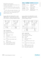
Shut-off with control signal w: In addition to relay override command situations, the damper will be fully closed if: (0 dm3/s or 0 m3/h) and control signal w falls below 0.5 - 2...10 VDC: HFB control signal w falls below 0.1 VDC - Both 0...10 VDC and 2...10 VDC: the airflow setpoint voltage falls below a value corresponding to an air velocity of less than 1.5 m/s Example: HFB; CU=EC (LMV-D2-MP HI), CU=EE (NMV-D2-MP HI) - variable airflow control with a room controller or a building management system Example: HFB; CU=EC (LMV-D2-MP HI), CU=EE (NMV-D2-MP HI) - parallel airflow control with a building...
Open the catalog to page 11All HALTON catalogs and technical brochures
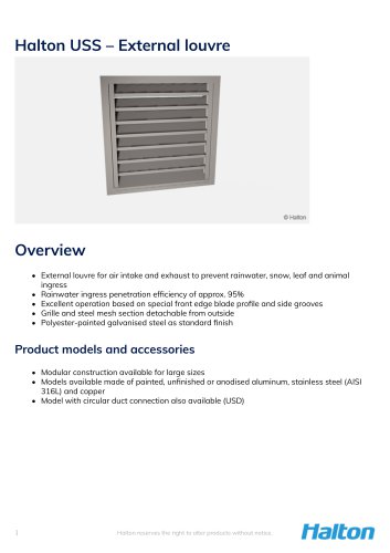 Halton USS
8 Pages
 Halton Vita Cell Room (VCR)
2 Pages
 Halton Rex Expander (RXP)
16 Pages
 Halton CBD
8 Pages
 FS Halton AHUs
28 Pages
 Halton KCD
3 Pages
 KVE-CM
7 Pages
 KMC - MobiChef
5 Pages
 Halton MobiChef
12 Pages
 R6B
R6B9 Pages
 Halton Vario
20 Pages
 Halton FDS
7 Pages
 Halton FDR
6 Pages
 Halton FDI
6 Pages
 Halton FDE
8 Pages
 Halton FDC
5 Pages
 ALE/ALU
8 Pages
 AHF
AHF5 Pages
 JTH
JTH4 Pages
 FDC
FDC5 Pages
 AFB
AFB7 Pages
 TCG 2013
4 Pages
 FCU 2013
6 Pages
 VHB - Active VAV Diffuser
7 Pages
 TLD - Wall Diffuser Unit
9 Pages
 FDB2 -
4 Pages
 CPA - Passive Chilled Beam
13 Pages


Archived catalogs
 KCJ
KCJ12 Pages
 HALTON-KSK
6 Pages
 HALTON-KVD
6 Pages
 FCU Vertical Fancoil Unit
4 Pages
 Halton ? Chilled Beams
12 Pages
 Halton ? Ventilation fire safety
12 Pages
 Halton ? AdaptableClimate
12 Pages
 HALTON-POLLUSTOP
4 Pages
 HALTON-KCE
10 Pages
 UNIPOINT
4 Pages
 Halton - universal grilles
46 Pages
 Halton - beam design guide
31 Pages


- Extractor hood
- Range hood with built-in lighting
- Industrial range cooker
- Ventilation grill
- Metal ventilation grill
- Electric range cooker
- Rectangular ventilation grill
- Commercial range cooker
- Hatch
- 1 oven range cooker
- Industrial air diffuser
- Aluminum ventilation grill
- Exterior ventilation grill
- Island range hood
- Metal access hatch
- Square ventilation grill
- Facade ventilation grill
- Ceiling-mounted air diffuser
- Industrial fan coil
- White ventilation grill