


Halton - beam design guide

1 / 31 PagesView full catalog
Halton - beam design guide
Product catalog summary
Overview
Halton's chilled beams are designed to improve indoor air quality and offer flexibility in building design. They are suitable for various environments, including offices and hospital wardrooms, and can be installed in both exposed and concealed settings. The product range includes active and passive chilled beams, as well as service beams that integrate multiple building services.
Halton's chilled beams are designed to improve indoor air quality and offer flexibility in building design. They are suitable for various environments, including offices and hospital wardrooms, and can be installed in both exposed and concealed settings. The product range includes active and passive chilled beams, as well as service beams that integrate multiple building services.
System Description
The chilled beam system is an air conditioning solution that uses water for efficient heat transfer, providing cooling, heating, and ventilation. It operates on the dry cooling principle to prevent condensation and is designed for spaces requiring good indoor climate control.
The chilled beam system is an air conditioning solution that uses water for efficient heat transfer, providing cooling, heating, and ventilation. It operates on the dry cooling principle to prevent condensation and is designed for spaces requiring good indoor climate control.
Ventilation
Active chilled beams use primary air to induce room air circulation, ensuring uniform air quality. Passive systems typically use ceiling or wall diffusers for air distribution.
Active chilled beams use primary air to induce room air circulation, ensuring uniform air quality. Passive systems typically use ceiling or wall diffusers for air distribution.
Cooling and Heating
Active beams offer high cooling capacities by recirculating room air through a heat exchanger. Heating integration is recommended when low heating capacity is sufficient, and window U-values prevent downdrafts.
Active beams offer high cooling capacities by recirculating room air through a heat exchanger. Heating integration is recommended when low heating capacity is sufficient, and window U-values prevent downdrafts.
System Design Strategies
Two main strategies are outlined: Adaptable and Traditional. The Adaptable strategy allows for flexibility in space usage and layout changes, while the Traditional strategy focuses on meeting initial design conditions with lower investment costs but higher costs for future changes.
Two main strategies are outlined: Adaptable and Traditional. The Adaptable strategy allows for flexibility in space usage and layout changes, while the Traditional strategy focuses on meeting initial design conditions with lower investment costs but higher costs for future changes.
Design Considerations
Key factors include indoor climate conditions, system flexibility, efficiency in logistics, and life cycle performance. The system should be designed to meet specific indoor climate targets, considering factors like room temperature, air velocity, and sound pressure levels.
Key factors include indoor climate conditions, system flexibility, efficiency in logistics, and life cycle performance. The system should be designed to meet specific indoor climate targets, considering factors like room temperature, air velocity, and sound pressure levels.
Important Technical Considerations
Ventilation should ensure adequate airflow rates and avoid draughts. Cooling capacities should align with airflow rates to maintain comfort. Heating systems should not be over-dimensioned, and window draughts should be minimized.
Ventilation should ensure adequate airflow rates and avoid draughts. Cooling capacities should align with airflow rates to maintain comfort. Heating systems should not be over-dimensioned, and window draughts should be minimized.
Heating and Cooling Specifications
- Active beams have a heating capacity of 150 to 250 W/m2 and require an inlet water temperature of 35-45°C for energy-efficient heating.
- Heating capacity is dependent on primary air flow rate, necessitating ventilation during heating.
- Static beams rely on primary air supply mixing and heat radiation from warmer upper spaces.
- Efficient control systems with room air temperature measurement are recommended for optimal heating control.
Chilled Beam Installation and Operation
- Chilled beams should be installed correctly to avoid draughts, especially near cold window surfaces.
- Halton Velocity Control (HVC) allows for manual adjustment of room air velocity with three positions: throttle, normal, and full.
- Halton Air Quality Control (HAQ) adjusts outdoor air flow rate and is crucial for meeting ventilation requirements.
Case Studies and Findings
- Studies show that HVC reduces draught discomfort and improves thermal comfort.
- Chilled beams installed perpendicularly to walls result in lower air velocities compared to parallel installations.
Chilled Beam Selection and Orientation
- Selection depends on factors like ventilation integration, indoor climate conditions, and energy efficiency.
- Perpendicular installation is preferred for lower occupied zone velocities.
Operation Range and Design Conditions
- Operation parameters are defined based on cooling and heating loads in representative rooms.
- Typical input values include room temperature, supply air temperature, and water inlet temperature.
Pre-selection and Selection Process
- Pre-selection involves using quick selection tables and software tools to choose the appropriate chilled beam model.
- Performance values are assessed based on parameters like air velocity, cooling and heating capacity, and sound level.
Chilled Beam System Design and Performance
1. Coil Capacity Calculation
Calculate the coil capacity using HIT Design by inputting the inlet and outlet water temperatures and target water flow rate. Compare the coil capacity against the requirement, noting capacities transferred by water and air sides.
Calculate the coil capacity using HIT Design by inputting the inlet and outlet water temperatures and target water flow rate. Compare the coil capacity against the requirement, noting capacities transferred by water and air sides.
2. Chilled Beam Location and Velocity Control
Define the location and number of chilled beams, allowing for asymmetric positioning. Adjust the throw pattern and velocity conditions using HVC positions to adapt to load variations.
Define the location and number of chilled beams, allowing for asymmetric positioning. Adjust the throw pattern and velocity conditions using HVC positions to adapt to load variations.
3. Air Quality Control Adjustment
Define the HAQ air flow rate to match the required room air flow rate. Adjust the air flow rate at a specified duct pressure level using HAQ control.
Define the HAQ air flow rate to match the required room air flow rate. Adjust the air flow rate at a specified duct pressure level using HAQ control.
4. Space Results and Unit Performance
Verify operation parameters against system conditions to ensure they correspond to the system's requirements.
Verify operation parameters against system conditions to ensure they correspond to the system's requirements.
5. Design Data in Heating
Conduct analysis similar to the cooling case to ensure proper heating performance.
Conduct analysis similar to the cooling case to ensure proper heating performance.
6. Management of Room Conditions
Implement air flow measurement by measuring the chamber pressure of the chilled beam. Adjust air and water flow rates using balancing dampers and valves. Use adaptable systems for efficient commissioning and operation.
Implement air flow measurement by measuring the chamber pressure of the chilled beam. Adjust air and water flow rates using balancing dampers and valves. Use adaptable systems for efficient commissioning and operation.
7. Room Control and Communication
Control room thermal conditions using two-way valves and various control methods. Implement communication over Ethernet for remote monitoring and operation.
Control room thermal conditions using two-way valves and various control methods. Implement communication over Ethernet for remote monitoring and operation.
8. Luminaire and Integrated Services Selection
Integrate luminaires and other services into chilled beams for improved indoor climate, flexibility, and reduced installation costs. Include occupancy sensors, control valves, and space for sprinklers.
Integrate luminaires and other services into chilled beams for improved indoor climate, flexibility, and reduced installation costs. Include occupancy sensors, control valves, and space for sprinklers.
9. Chilled Beam Selection Example
Provide examples of chilled beam selection for different room configurations, detailing cooling and heating capacities, air flow rates, and operational parameters.
Provide examples of chilled beam selection for different room configurations, detailing cooling and heating capacities, air flow rates, and operational parameters.
Room Specifications
Room A: Size: 4.2 x 2.7 x 3.0 m, Cooling Capacity: 674 W, Heating Capacity: 411 W, Inlet/Outlet Water Temperature: 15.0/19.1 °C for cooling, 35.0/29.8 °C for heating, Water Massflow: 0.030 kg/s for cooling, 0.020 kg/s for heating, Supply Air Temperature: 18.0 °C for cooling, 20.0 °C for heating, Sound Pressure Level: 21 Lp.
Room B: Size: 4.2 x 4.0 x 3.0 m, Total Cooling Power: 956 W, Inlet/Outlet Water Temperature: 15.0/18.8 °C, Water Massflow: 0.045 kg/s, Supply Air Temperature: 18.0 °C, Sound Pressure Level: 24 Lp.
Room C: Size: 4.2 x 4.0 x 3.0 m, Total Cooling Power: 1116 W, Inlet/Outlet Water Temperature: 15.0/20.1 °C, Water Massflow: 0.040 kg/s, Supply Air Temperature: 18.0 °C, Sound Pressure Level: 19 Lp.
Room D: Size: 4.2 x 8.1 x 3.0 m, Total Cooling Power: 2394 W, Inlet/Outlet Water Temperature: 15.0/20.7 °C, Water Massflow: 0.060 kg/s, Supply Air Temperature: 18.0 °C, Sound Pressure Level: 30 Lp.
Room A: Size: 4.2 x 2.7 x 3.0 m, Cooling Capacity: 674 W, Heating Capacity: 411 W, Inlet/Outlet Water Temperature: 15.0/19.1 °C for cooling, 35.0/29.8 °C for heating, Water Massflow: 0.030 kg/s for cooling, 0.020 kg/s for heating, Supply Air Temperature: 18.0 °C for cooling, 20.0 °C for heating, Sound Pressure Level: 21 Lp.
Room B: Size: 4.2 x 4.0 x 3.0 m, Total Cooling Power: 956 W, Inlet/Outlet Water Temperature: 15.0/18.8 °C, Water Massflow: 0.045 kg/s, Supply Air Temperature: 18.0 °C, Sound Pressure Level: 24 Lp.
Room C: Size: 4.2 x 4.0 x 3.0 m, Total Cooling Power: 1116 W, Inlet/Outlet Water Temperature: 15.0/20.1 °C, Water Massflow: 0.040 kg/s, Supply Air Temperature: 18.0 °C, Sound Pressure Level: 19 Lp.
Room D: Size: 4.2 x 8.1 x 3.0 m, Total Cooling Power: 2394 W, Inlet/Outlet Water Temperature: 15.0/20.7 °C, Water Massflow: 0.060 kg/s, Supply Air Temperature: 18.0 °C, Sound Pressure Level: 30 Lp.
General Observations
- Heat sources and their location can influence the velocity and direction of the air jet.
- Maximum velocity in the occupied zone should not exceed 0.20 m/s to ensure comfort.
- Temperature differences and dew point temperatures are critical for system efficiency and comfort.
See more
Catalog excerpts

alton - Chilled Beams Care for IndoorAir Malton CARE FOR INDOOR AIR
Open the catalog to page 1All HALTON catalogs and technical brochures
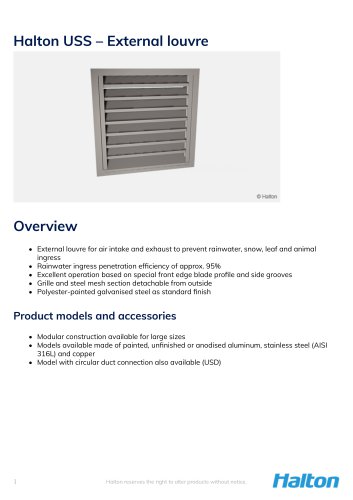 Halton USS
8 Pages
 Halton Vita Cell Room (VCR)
2 Pages
 Halton Rex Expander (RXP)
16 Pages
 Halton CBD
8 Pages
 FS Halton AHUs
28 Pages
 Halton KCD
3 Pages
 KVE-CM
7 Pages
 KMC - MobiChef
5 Pages
 Halton MobiChef
12 Pages
 R6B
R6B9 Pages
 Halton Vario
20 Pages
 Halton FDS
7 Pages
 Halton FDR
6 Pages
 Halton FDI
6 Pages
 Halton FDE
8 Pages
 Halton FDC
5 Pages
 ALE/ALU
8 Pages
 AHF
AHF5 Pages
 JTH
JTH4 Pages
 FDC
FDC5 Pages
 AFB
AFB7 Pages
 TCG 2013
4 Pages
 FCU 2013
6 Pages
 HFB - Airflow Management Damper
17 Pages
 VHB - Active VAV Diffuser
7 Pages
 TLD - Wall Diffuser Unit
9 Pages
 FDB2 -
4 Pages
 CPA - Passive Chilled Beam
13 Pages


Archived catalogs
 KCJ
KCJ12 Pages
 HALTON-KSK
6 Pages
 HALTON-KVD
6 Pages
 FCU Vertical Fancoil Unit
4 Pages
 Halton ? Chilled Beams
12 Pages
 Halton ? Ventilation fire safety
12 Pages
 Halton ? AdaptableClimate
12 Pages
 HALTON-POLLUSTOP
4 Pages
 HALTON-KCE
10 Pages
 UNIPOINT
4 Pages
 Halton - universal grilles
46 Pages


Related Searches
- Extractor hood
- Range hood with built-in lighting
- Industrial range cooker
- Ventilation grill
- Metal ventilation grill
- Electric range cooker
- Rectangular ventilation grill
- Commercial range cooker
- 1 oven range cooker
- Industrial air diffuser
- Exterior ventilation grill
- Hatch
- Aluminum ventilation grill
- Island range hood
- Metal access hatch
- Facade ventilation grill
- Square ventilation grill
- Ceiling-mounted air diffuser
- Industrial fan coil
- White ventilation grill
*Prices are pre-tax. They exclude delivery charges and customs duties and do not include additional charges for installation or activation options. Prices are indicative only and may vary by country, with changes to the cost of raw materials and exchange rates.