Catalog excerpts
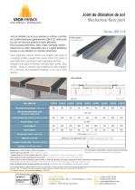
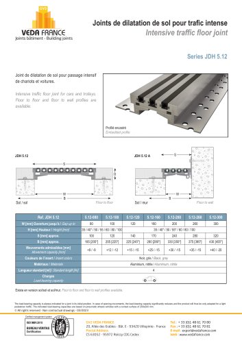
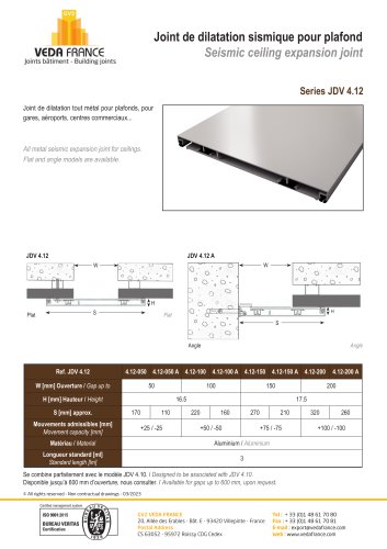
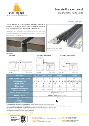
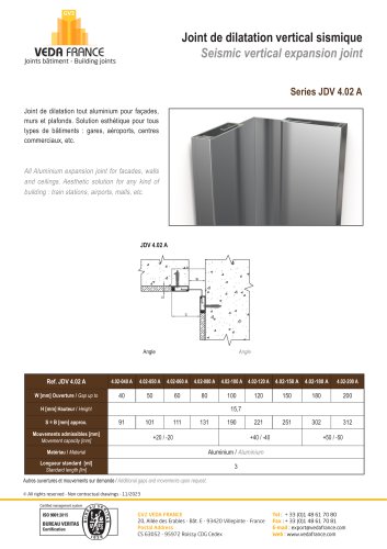
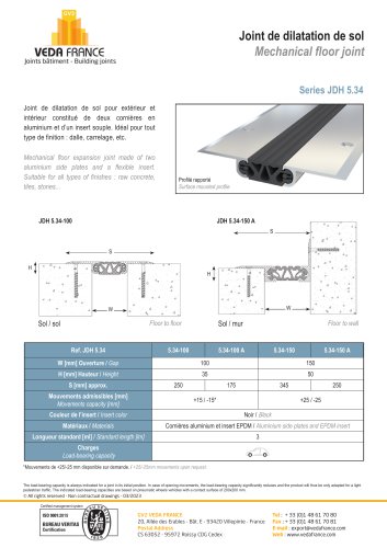
mm V€Dn FRRNC6 Joints batiment - Building joints Joint de dilatation de sol Mechanical floor joint Series JDH 5.18 Joint de dilatation de sol pour exterieur et interieur constitue de 2 profiles identiques (generalement JDH 5.02), relies entre eux par une structure portante en acier galvanise. Pour tous types de finitions : dalle, chape, carrelage, marbre... Capots inox ou laiton disponibles pour un aspect esthetique luxueux ou une utilisation en industrie alimentaire. Floor expansion joint for interior and exterior use made of 2 identical profiles (usually from series JDH 5.02) linked to each other with a galvanized steel supporting structure. Suitable for all types of finishes: concrete slab, screed, tiles, marble... Brass or stainless steel capping are also available for a luxurious and aesthetical finishing, or for use in food industry. Ref. JDH 5.18 W [mm] Ouverture jusqu’a / Gap up to Mouvements admissibles [mm] Movement capacity [mm] L [mm] Largeur bac central / Central pan width H [mm] Hauteur / Height S [mm] approx. B [mm] approx. Noir ou gris / Black or grey Aluminium, acier galvanise, nitrile / Aluminium, galvanized steel, nitrile Couleurs de l’insert / Insert colors Materiaux / Materials Longueur standard [ml] / Standard length [lm] Charges / Load bearing capacity Modele de joint : JDH 5.02-060 ou JDH 5.04 renforcee. / Joint reference:Series JDH 5.02-060 or reinforced JDH 5.04. Pour toute etude ou preconisation, consulter notre service technique. *Autres hauteurs sur demande. / Other heights upon request. P'ease mfer to our techmcal department for specification. **Hauteur totale (H) = 50 mm. Hauteur Libre (HL) = 44 mm. / Total height (H) = 50mm. Free height (HL) = 44mm. Thermosoudures d’insert preconisees pour les raccords. / Hot-welding recommended for junction of the flexible insert. Mettre en place un treillis soude dans la partie centrale, au milieu de l’epaisseur de la chape a realiser afin d’eviter la fissuration du revetement central. / Install welded wire mesh in the central pan, at the center of the screed in order to avoid cracks of the finish installed in the pan. Video d’installation et fiche de pose disponibles sur demande. / Installation video and installation instruction upon request. The load-bearing capacity is always indicated for a joint in its initial position. In case of opening movements, the load-bearing capacity significantly reduces and the product will thus be only adapted for a light pedestrian traffic. The indicated load-bearing capacities are based on pneumatic wheels vehicles with a contact surface of 200x200 mm. © All rights reserved - Non contractual drawings - 03/2023 20, Allee des Erables - Bat. E - 93420 Villepinte - France Fax : + 33 (0)1 48 61 70 81 Postal Address E-mail : export@vedafrance.com CS 63052 - 95972 Roissy CDG Cedex Web : www.vedafrance.com
Open the catalog to page 1All GV2 VEDA FRANCE catalogs and technical brochures
-
 Control joints - JF 800
1 Pages
-
 Control joints - JF 600
1 Pages
-
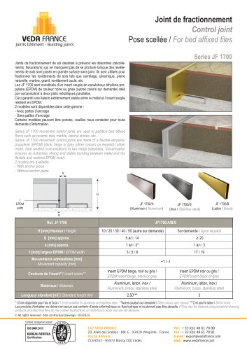 Control joints - JF 1700
1 Pages
-
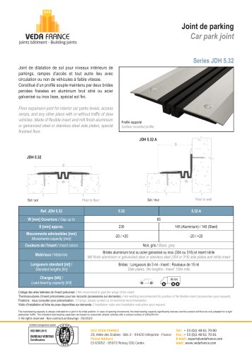
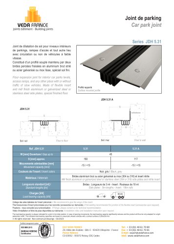 Car park joint - JDH 5.31
1 Pages
-
 Antislip adhesive tape
2 Pages
-
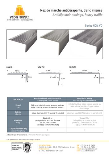 Stair nosing - Series NDM VD
1 Pages
-
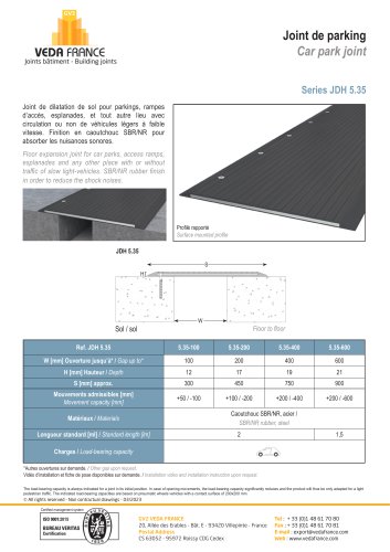 Car park joint - JDH 5.35
1 Pages
-
 THE RANGE
64 Pages
-
 JDH 6.11
1 Pages
-
 VEDAFEU N FIRESTOPS BLANKETS
2 Pages
-
 VEDAFEU M FIRESTOPS BLANKETS
3 Pages
-
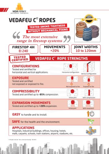 VEDAFEU C FIRESTOPS ROPES
6 Pages
-
 COMPRESSION PROFILES CP
1 Pages
-
 COMPRESSION PROFILES - PSR
1 Pages
-
 JOINT COVER - CJP
2 Pages
-
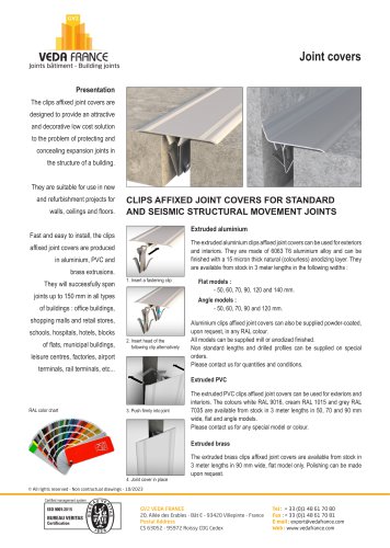 Joint covers
2 Pages
-
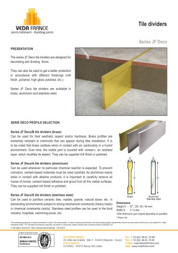 Control Joints - JF Deco
1 Pages
-
 Control joints - JF 1600
1 Pages