- Catalogs
- Guntamatic Heiztechnik GmbH
- Planning documents
Planning documents
Planning documents
This document provides guidelines for integrating the BIOSTAR FLEX/Box/W pellet boiler into heating systems, serving as a reference for customers and engineers.
The BIOSTAR boiler features a durable fire clay combustion chamber with variable output regulation, efficient operation, reduced emissions, and a user-friendly interface. It requires minimal maintenance with automatic ash removal and heat exchanger cleaning.
Different models of the BIOSTAR boiler, including FLEX, BOX, and W types, are outlined, each with specific features and capacities.
Initial operation must be conducted by a Guntamatic engineer. Operators should adhere to installation and operating instructions.
- Appliance Dimensions: Installation guidelines based on house insulation and size.
- Annual Fuel Consumption: Pellet requirements per kW output.
- Boiler Room: Specifications for installation site, including temperature and space requirements.
- Pellet Storage Room: Design guidelines for efficient storage and delivery of pellets.
The system is designed for wood pellet fuel, with storage configurations for annual supply.
Includes additional technical data and attachments for reference.
Compliance with Austria's F90/T30 standards for the Biostar BOX flexible connection; no regulations in Germany for systems up to 50 KW.
Part of the flexible coupling connection, with pricing available upon inquiry.
External installations require rain and UV protection.
Filler couplings can be installed on walls or in light wells, with specific considerations for foam selection, earthing, and distance from walls.
Requirements for venting exhaust gases, including heat insulation and moisture resistance. Flue height varies based on boiler capacity.
Data for calculating flue cross-sections and the necessity of a flue draw regulator.
Includes various connections and requires an expansion chamber based on system volume.
Specific wiring requirements for external sensors and room stations.
Optional weather-controlled heating circuit regulators are available, with a buffer needed when combined with solar power.
Designed for wood pellets, which are environmentally friendly and CO2-neutral.
Includes dimensional drawings and hydraulic diagrams, as well as remote control capabilities.
- Models: BIOSTAR 12, 15, 23
- Type: HX FLEX W
- Automatic Ash Removal: Optional for BIOSTAR 12 and 15, Yes for BIOSTAR 23
- Nominal Heating Capacity: 12 kW, 15 kW, 23 kW respectively
- Modulation to Smallest Load: 3.3 kW, 3.5 kW, 6.9 kW respectively
- Exhaust Gas Connection Diameter: 125 mm internal / 130 mm external
- External Dimensions: 1056 x 914 x 1567 mm for BIOSTAR 12 and 23; 1620 x 914 x 1950 mm for BIOSTAR 15
- Weight: 298 kg + 140 kg for BIOSTAR 12, 300 kg + 140 kg for BIOSTAR 15, 305 kg for BIOSTAR 23
- Flue Draw Nominal Load: 10 Pa for BIOSTAR 12 and 15, 15 Pa for BIOSTAR 23
- Boiler Efficiency: Approximately 90% for all models
- Exhaust Gas Temperature: Nominal load 160°C to 180°C, Partial load 101°C to 105°C
- CO Emissions: 70 mg/Nm3 for BIOSTAR 12, 47 mg/Nm3 for BIOSTAR 15, 44 mg/Nm3 for BIOSTAR 23
- Max Power Consumption: 1400 W for all models
- Electrical Connection: 230 VAC / 50 Hz / 10 A
- Fuel Quality: ÖNORM 7135 Pellets
- Boiler Water Content: 30 liters for BIOSTAR 12 and 15, 37 liters for BIOSTAR 23
- Boiler Minimum Flow: 520 l/h for BIOSTAR 12, 650 l/h for BIOSTAR 15, 1000 l/h for BIOSTAR 23
- Permissible Operational Pressure: 3 bar
- Weight with Auger: 30 kg
- Max Torque Speed: 120 Nm
- Maintenance: Maintenance-free
- Suction Tank Capacity: 100 liters
- Max Length of Suction Lines: 20 m (15 m for one floor)
- Refill Time: 8 – 10 minutes
- Address: A-4722 Peuerbach, Bruck-Waasen 7
- Phone: 07276/2441-0
- Email: [email protected]
- Website: www.guntamatic.com
Catalog excerpts
10/07 Planning documents Biostar Planning documents BIOSTAR Flex / Box / W
Open the catalog to page 1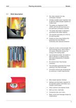
10/07 Planning documents Biostar 1.1 Brief description Hot, wear-resistant fire clay combustion chamber Infinitely variable output regulation due to optimum pellet dosage supplied via a feed chute The pellets are degassed at 800-1000°C with the aid of primary air in the optimised combustion chamber The ember bed height is adjusted in accordance with output capacity The requisite secondary air is fed via the spinning plate A good mix and a long holding time guarantee the most efficient combustion with reduced emissions. Օ using the counter current principle, the heat exchange ducts, which follow...
Open the catalog to page 3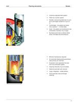
10/07 Planning documents Biostar Customer-adjusted feed system Feed via a suction system Flexible, overcoming distances of up to 20 m and height variations of up to 5 m. Comfortable - the pellets are drawn into a cyclone 1 - 2 times daily. Quiet - the pellets are transferred to the combustion chamber via an auger. Burnback-proof due to cellular wheel sluice, fall steps and low pressure. Minimal maintenance required An automatic tipping grate guarantees clear primary air channels Expansion zone separates the dust from the combustion gases Cleaning intervals of up to 8 weeks Optional automatic...
Open the catalog to page 4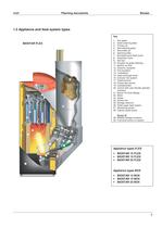
10/07 Planning documenls Biostar 1,2 Appliance and feed System types Key BIOSTAR FLEX t. Ash gntos 2. Grate cleanmg 1 Primary -i ir i Sert cteaning grate 5. Secondt? air 6. Spnrtng piete 7. Burr*>ack-prool1e^ chute 9. Ashbcv 10 ActuaK* lot grate clearing 11P tgnibon u ftatt 12, Ceramic *nsulat>or> 13. Full ineulaflon 14- Turtoulaor* 15 heat«xchanotdudt 16. Extractoi⮮nnsyttem 17. Cteaning lover 18. SmoKe gas §#n$or 19. Lambda probe 20. Conlrol wKh ueerftondly opefalor interface 22 Mplor 23. Gee/i 24 Suctontan 25. Sfcxage reeervor 26 PeWauger teed»vite<n 27 MonrtonrQ senior 28 Ceiulat wneel akitce...
Open the catalog to page 5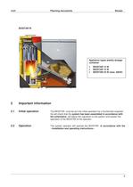
10/07 Planning documenls Biostar BIOSTAR V/ 2 Important information 2.1 Initial opration The BIOSTAR mustbe put inio initial opration by a Guntamaticengineer. He will check Ihal the System has been assembled In accordanco wlth the schematlcs. will adjust the r驩gulation to the System and explain the opration of the BIOSTR to the operalor. 2.2 Op逩ration The System operalor will operate the BIOSTAR In accordanco wlth the «Installation and operating Instructions». 6
Open the catalog to page 6
10/07 Planning documents Biostar 3 Planning 3.1 Appliance dimensions Guide values for installing the Biostar pellet boiler: Poorly insulated housemax. 140 m2 heated living space 12 KW New house max. 170 m2 heated living space 12 KW Low energy house max. 240 m2 heated living space 12 KW Poorly insulated house max. 160 rri2 heated living space 15 KW New housemax. 220 m2 heated living space 15 KW Low energy house max. 300 m2 heated living space 15 KW Poorly insulated house max. 230 m2 heated living space 23 KW New house max. 300 m2 heated living space 23 KW Low energy house max. 400 m2 heated living...
Open the catalog to page 7
10/07 Planning documents Biostar 3.3 Boiler room Please see the valid boiler room specification for the relevant requirements. The boiler room must be frost-proof. When the system is in operation, the boiler room temperature must lie between 10-40 °C. Key A Installation site entrance B Pellet boiler C Combustion air supply D Outlet for safety valve E Electrical connection F Outreach front door G Flue diameter H Admixed air installation as draw limit, cleaning aperture and pressure relieving flap 8
Open the catalog to page 8
10/07 Planning documents Biostar Important: The boiler room, flue, heating system and electrical installation must all comply with the relevant standards and legal specifications. Installation to site The BIOSTAR FLEX/BOX/W is delivered with full wiring and insulation. Including insulation, the boiler has a width of 1056 mm and a depth of 914 mm. (Boiler dimensions without insulation: width: 650 mm; depth 640; height 1500 mm). The entrance to the installation site should therefore be a minimum of 700 mm wide. Installation site Place the system close to the flue, in order to avoid a lengthy exhaust...
Open the catalog to page 9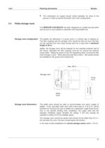
10/07 Planning documents Biostar The combustion air supply should, where possible, be close to the ground, in order to prevent the boiler room from cooling down. 3.4 Pellet storage room The BIOSTAR FLEX/BOX/W has been designed as a pellet burning boiler and as such is only suitable for operation with wood pellet fuel. Storage room configuration The pellets are delivered in a pump truck in a similar way to heating oil. The filler coupling and the storage room should be laid out such that they can be reached from the house access point by a hose with a maximum length of 30 m. Ideally, the storage...
Open the catalog to page 10
10/07 Planning documents Biostar Per 1 kW heating load = 0.85 m3 Storage room (vacuum feeding system FLEX) Օ Per 1 KW heating load = 360-400kg pellets (Biostar Box) In the case of wide storage rooms (width > 2.5 m): Per 1 kW heating load = 1.2-1.3 m3 storage room Storage room design Please note the following criteria: Օ The storage room must be dry and airtight The storage room walls must be as per F90 and surface hard, doors T30 (A) Օ All openings to the storage room must be sealed and dust-tight (doors, accesses...) No switches, sockets, lighting or distribution boxes are permitted in the...
Open the catalog to page 11
10/07 Planning documents Biostar Planning example: Storage room Biostar FLEX 12
Open the catalog to page 12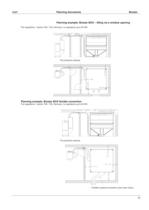
10/07 Planning documents Biostar Planning example: Biostar BOX - filling via a window opening Fire rgulations: Austria: F90 / T30, Germany: no rgulations up to 50 KW Planning example: Biostar BOX flexible connection Fire regulations: Austria: F90 / T30, Germany: no regulations up to 50 KW Flexible coupling connection, price upon inquiry 13
Open the catalog to page 13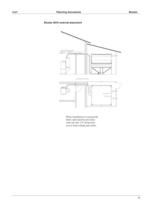
10/07 Planning documents Biostar Biostar BOX external placement When installation is external the fabric tank must be provided with rain and UV protection. (cover from ceiling and walls). 14
Open the catalog to page 14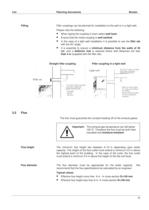
4/04 Planning documents Biostar Filling Filler couplings can be planned for installation to the wall or in a light well. Please note the following: When laying the coupling in foam select well foam Օ Ensure that the metal coupling is well earthed In the case of a light well installation it is possible to use the filler set with the 45° angle Օ It is essential to ensure a minimum distance from the walls of 30 cm, and a deflector mat is required where wall distances are less than 4 m (supplied with the filler set). Straight filler coupling Filler coupling in a light well Filler set Light well...
Open the catalog to page 15All Guntamatic Heiztechnik GmbH catalogs and technical brochures
 1963 GUNMATIC
16 Pages
 Prospectus
24 Pages
 Biocom
20 Pages
 Biostar
20 Pages
- Industrial heat pump
- Indoor boiler
- Domestic boiler
- Residential heat pump
- Air source heat pump
- Outdoor heat pump
- Industrial water heater
- Gas boiler
- Inverter heat pump
- Vertical water heater
- Energy rating heat pump
- Split heat pump
- Commercial heat pump
- Heating only boiler
- Wall-mounted boiler
- Energy rating boiler
- Class A++ heat pump
- Commercial boiler