Installation Manual
1 /17Pages

Installation Manual
1 /17Pages
Catalog excerpts

Installation Manual Grodan GroSens MultiSensor System Grodan Part of the ROCKWOOL Group
Open the catalog to page 1
Installation Manual Installation Manual 3 Software installation Smartbox 4 Connection to climate computer 2.6 How to install the Sensors 2.7 Setting the correct plate 3.8 Slab types - setting the correct type slab 13 3.9.2 Row and offset -configuring a Sensor 16 3.11 System date, time and authorisation levels
Open the catalog to page 2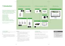
Installation Manual Installation Manual → Climate computer cabinet ← → Monitoring ← Remote access via Internet Browser GroSens Receiver This manual will guide you through the installation of the Grodan GroSens System. The GroSens System consists of several separate components: GroSens Extender GroSens Sensors GroSens Receiver GroSens Reader GroSens Smartbox GroSens Convertor Ethernet Extender (if required) Power over Ethernet (PoE) injector Network switch GroSens Convertor GroSens Reader Climate computer software package GroSens Smartbox All elements of a standard GroSens System are described...
Open the catalog to page 3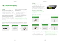
Installation Manual Installation Manual 2.1 General Before starting to install the system, the rough location of the GroSens Sensors should be defined. The maximum distance from the GroSens Sensors to the GroSens Receiver is 50 meters. Due to the growth of the crop, the distance will be larger at the start of the season than at the end. The Sensors that are in the same irrigation section should be used to calculate the average of that section. As shown in the overview, the GroSens Smartbox, GroSens Receiver and GroSens Convertor need to be connected to the LAN. Most growers also have a specific...
Open the catalog to page 4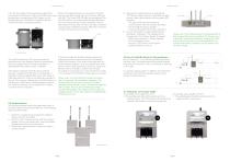
Installation Manual First, the long cable into the greenhouse should be connected to the Receiver. The correct RJ45 outlet must be used when connecting the PoE injector to the GroSens Receiver. The outlet is located inside the GroSens Receiver housing (see below). Installation Manual When the GroSens Receiver is connected to the PoE Injector, two LEDs should light up: the Power LED and Link LED. The Power LED will light up immediately. The link LED will turn on as soon as the GroSens Receiver has auto-discovered the GroSens Smartbox; this can take several minutes. Wait until the Link LED is lit...
Open the catalog to page 5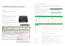
Installation Manual Installation Manual 3.3 Devices section (shortcut button so ) 3 Software installation Smartbox The devices overview shows how your Grosens System is configured in the greenhouse in a non-graphical format. It also tells you how the complete systems are operating. 3.1 General All hardware is preinstalled with the standard software necessary. This section highlights the steps necessary to apply custom settings. The information from the Sensors is displayed in table format, grouped by irrigation section. The information from the Reader, Converters and Receivers is grouped in a separate...
Open the catalog to page 6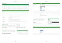
Installation Manual Installation Manual • Section Settings • Monitoring - Add Sensor - Select Sensor - Row and Offset - configure a Sensor • Irrigation Control - connect a Converter 3.5 Other devices Field/Function 3.6 Create new section This function allows you to create and configure an irrigation section in which Sensors can be placed. When you select this function, the following picture will appear and display the section settings. There are three subscreens to complete: 3.8 Slab types - setting the correct slab type In this menu you can configure the slab type that applies to your greenhouse....
Open the catalog to page 7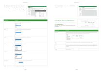
Installation Manual Installation Manual You will be taken back to the main screen, where your designed slab can be found in the menu bar. Click your named slab type and then "Edit". This will take you to a menu bar where you can enter the correct settings the settings. After clicking "Apply", you will see a summary of the configured slab type: 3.9 Monitoring - adding and configuring Sensors Length You can select the appropriate length from the dropdown list: 3.9.1 Adding Sensors When you click "Monitoring", the window shown right will appear. You can select the appropriate width from the dropdown...
Open the catalog to page 8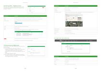
Installation Manual Installation Manual 3.9.2 Row and offset - configuring a Sensor When you click the row or offset number in the screen, you will see the following window which allows you to configure a Sensor: Field/Function Description Field/Function Natural Lighting Description Check this option if you are using natural lighting. Shows the latitude. Shows the longitude. When you click this function, you will be taken to Google Maps to help you find the appropriate latitude and longitude. You can copy and paste the values into this page. i^VjtLDPf] This is the row in which the GroSens Sensor...
Open the catalog to page 9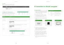
Installation Manual Installation Manual 3.12 Update When you click this function, the system will check whether there are any software updates available. gn>dan GROSENS DaslibM'd - fwlbnya ■ ■ Rtpwts • Hdp - EngBsJi • ilfsQpBdIAcum 4 Connection to climate computer ;; SO * T^n pjgtwe ,ri. In14x1*1nSumrer-r CKrtlrtj, fc* IIHUIUH Enter email address Specify the username in this field in the form of an email address. User Password Enter the password in this field. 4.1 Hardware Installation 1. The GroSens Convertor has the following outputs: Check whether the climate computer has 3 free analogue...
Open the catalog to page 10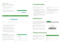
Installation Manual Installation Manual Installation Manual Installation Manual 4.2 Software installation After following the procedure for the hardware installation of the Convertor and when the Link LED is constantly lit, the following steps need to be completed: 1. Click on the cog wheel of the section, the connvertor should be assigned to 2. Click "irrigation settings" 3. Irrigation control - connecting a Converter Clicking the "Irrigation Control" tab takes you to the following window, in which you can configure a Converter: If no graph is visible on the web user interface or climate computer,...
Open the catalog to page 11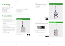
Installation Manual Installation Manual For Warranty information, please contact our Customer Service Departments. For other countries contact the head office: Rockwool BV - Grodan Industrieweg 15 5045 JG Roermond the Netherlands Phone : (31) 475 353 020 email: [email protected] www.grodan.com For US and Canada: Roxul Inc. - Grodan 8024 Esquesing Line Milton ON L9T 6W3 Canada Phone : (1) 905 636 0611 9 Appendices 9.1 Sensor The GroSens Sensors have two functions: 1. They perform measurements in the slab at a regular time interval. To determine the right measurement location of the Sensor, see Section...
Open the catalog to page 12All GRODAN catalogs and technical brochures
 Grodan Prestige
3 Pages
 grotop-master-dry
4 Pages
 GT Master NG2.0
2 Pages
 Plantop Dry NG2.0
2 Pages
 Grodan Vital NG2.0
2 Pages
 grodan knowledge & advice
2 Pages
 Grodan plugs
2 Pages