GIP-ENG-07-2020
1 /60Pages

GIP-ENG-07-2020
1 /60Pages
Catalog excerpts
FACADE SUBSTRUCTURES
Open the catalog to page 1
Photo credits: Page 5 Page 6 Page 10-11 Page 12 Page 13 Page 14-15 Page 18 Page 29 Page 30 Page 31 Page 32 Page 33 Page 34 Page 35 Page 36 Page 37 Page 38 Page 39 Page 40 Page 41-1 Page 41-2 Page 41-3 Page 41-4 Page 57 Innside Hotel, Wolfsburg, Germany, ALU-BAU Grabner GmbH Main State Archive in Magdeburg, Germany, Lothar Sprenger Kindergarten, Copenhagen, Denmark, CREATON AG www.fotolia.com Esch Belval, Luxemburg, Wienerberger GmbH; www.fotolia.com Nordkopftower, Wolfsburg, Germany, ALU-BAU Grabner GmbH Library, Litzendorf, Germany, FLEISCHER Metallfaszinationen Office building of Peine Water...
Open the catalog to page 2
FACADE SUBSTRUCTURES
Open the catalog to page 3
2. Structural components of the VCW facade system 7 - VECO® wall brackets 19 - Substructures with no thermal bridges 22 - End profiles, moldings and window frames 29 7. VECO® substructure systems 42
Open the catalog to page 4
FOREWORD Ventilated curtain walls (VCWs) have been established in the construction industry in Germany and Europe for decades. Over this time they have proven their worth as rugged construction systems requiring very little maintenance. Moreover, ventilated curtain walls enable architects to create a wide range of fascinating designs. GIP GmbH is a manufacturer of metal substructure systems for VCWs and an experienced consulting partner in all technical matters relating to the design, planning and realisation of ventilated curtain walls. This document provides a brief description of the basic...
Open the catalog to page 5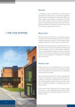
General A ventilated curtain wall (VCW) is a facade system composed of multiple layers, in which the supporting external wall is provided with a facing that offers protection against the weather. The facing can be made from a wide variety of materials: ceramic, metal, fibre cement, composite panels, natural stone etc. The substructure attaches this facing to the solid outer wall while leaving a gap between the two. Mechanism Wind and thermal effects due to warming create a circulation of air in the ventilation space. This circulation transports away the moisture in the ventilation space caused...
Open the catalog to page 6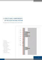
2. STRUCTURAL COMPONENTS OF THE VCW FACADE SYSTEM The typical structure of the facade system is shown below. 1_ Wall brackets 2_ Facade anchors 3_ Facade fastener anchors 4_ Vertical profiles 5_ Thermal insulation 6_ Ventilated substructures 7_ Fastening elements for the cladding (rivets, ceramic clips, polymer adhesives or similar) 8_ Cladding panels (ceramic, metal, fibre cement, composite)
Open the catalog to page 7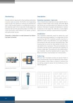
Facade anchors approved by the building authorities must be used to anchor the VCW to the supporting external wall. The optimum anchors are selected for use in each project based on considerations such as the materials used in the construction of the supporting external wall and the prevailing loads. For VCWs, the most commonly used anchors are plastic anchors with galvanised screws. Suitable insulation materials: Only mineral wool materials may be used for the insulation of VCW. These must comply with DIN 18516 and hence be non-flammable and absorb very little moisture. Standard insulation thicknesses...
Open the catalog to page 8
Substructure The substructure transmits the load of the cladding itself and the wind load to the enclosing external wall. Metal substructures are generally used as these can compensate for tolerances in the shell construction. Most systems consist of a two-part construction, which is fastened to the supporting external wall using a nchors. This base construction is aligned plumb and flush and acts as a support for installing a variety of facade cladding materials. The substructure system must be designed in such a way that materials used can expand due to temperature changes without creating...
Open the catalog to page 9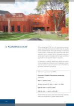
3. PLANNING A VCW When designing a VCW, as in all construction projects, proper planning and execution determine the quality of the finished facade. Although damage to ventilated curtain walls is extremely rare compared with other systems, and is usually due to incorrect execution, careful planning that considers all the basic conditions applicable to the specific object is required. In Germany, a range of regulations, which are continuously updated give planners and installation companies the necessary security in the areas of invitations to tender, execution and billing. Technical regulations...
Open the catalog to page 10
Calculation of the thermal transmission rating / Consideration of thermal transmission German Energy Saving Regulation (EnEV) In addition to considering its primary energy consumption, a building’s thermal insulation certificate also includes the calculation of the heat energy loss through its external walls. In the case of VCWs, there has been growing interest in the thermal bridge effect of the bracket design over recent years. These energy losses are taken into account by the so-called thermal bridge loss coefficient per bracket. There are several conceivable approaches to reducing the energy...
Open the catalog to page 11
Calculation method of EnEV Whether and how the certification process in accordance with EnEV must be performed depends, among other things, on whether the structure is a new building or an existing one which is being altered. EnEV 2016 replaced the previous regulation introduced in 2014 and has introduced more stringent standards. In addition, EnEV 2016 requires a further improvement of around 25 percent in the thermal insulation of building envelopes in new buildings from 1 January 2016. The benchmark is the specific transmission heat loss (H’t) of the new building measured in W/(m² K) over...
Open the catalog to page 12
Wind load Wind load is one of the factors caused by climatic conditions, which has a variable effect on buildings. It results from the pressure distribution around a structure, which is subject to a wind flow. It generally acts as an area load perpendicular to the contact surface and is primarily a combination of pressure and suction. The slowing of the air current creates an overpressure on the frontal surfaces exposed to the wind. In the areas of the roof and side surfaces, the air current dissipates at the edges of the building creating an underpressure (suction) at these locations. An underpressure...
Open the catalog to page 13All GIP GmbH catalogs and technical brochures
 GIP Substructures
2 Pages
 GIP Facade Catalogue
60 Pages
Archived catalogs
 Facade Substructures
60 Pages
- Panel rainscreen cladding
- Metal cladding
- Smooth rainscreen cladding
- Building fastening system
- Ventilated facade rainscreen cladding
- Composite cladding
- Exterior mounting clip
- Vertical cladding
- Aluminum fastening system
- Ceramic cladding
- Facade cladding fastening system
- Fiber cement cladding
- Facade fastening system
- Concealed fastening system