

GW13 12 06 02
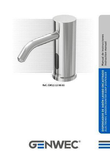
GW13 12 06 02
Introduction and Product Overview
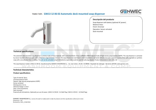
The Genwec GW13 12 06 02 is an automatic under-counter soap dispenser designed for countertop installation. It features a brass main body with an integrated bent cannula and an infrared (IR) sensor for automatic soap dispensing upon hand detection. The dispenser includes a 1000 ml plastic soap bottle, a control unit with a quick-fill button, a metal fixation base, internal soap tubing, and a DC power supply (battery box or 100-240 VAC to 6 VDC adapter). The sensing distance is adjustable between 50 and 220 mm, and the device supports most hand-washing soaps within specified pH and viscosity ranges.
Main Technical Specifications
- Power Supply: 6 VDC (via adapter 100-240 VAC, 50/60 Hz)
- Power Consumption: Standby < 0.5 mW, Operating < 5 W
- Sensing Distance: Adjustable 50 – 220 mm
- Soap Dispensed per Use: 0.6 – 2.0 ml
- Bottle Capacity: 1000 ml
- Operating Temperature: 1 – 55 ºC
- Compatible Soap pH: 5 – 9
- Compatible Soap Viscosity: 1 – 1500 cps
Components and Installation
Components: IR sensor, brass main body, control unit with button, soap bottle, battery box, soap tubing, fixation plate, washers, nuts, plastic wall plugs, and screws.
Installation Steps:
- Main Body: Insert the brass body into the countertop hole, connect sensor wiring, power cable, and soap tube, then secure with rubber washer and nut.
- Control Unit: Mount the metal bracket on the wall using supplied screws and plugs, attach the soap bottle filled with soap.
- Battery Box: Mount on the wall near the control unit, insert batteries with correct polarity, close the box, and connect wiring.
- Connections: Connect black terminals between faucet and control unit, red terminals between faucet and power supply, and connect soap tubes as per diagram.
- Initial Setup: After powering on, the dispenser auto-adjusts sensing distance. Press the quick-fill button to prime the soap tube, then test dispensing by placing hands in detection zone.
Important Installation Notes: Avoid direct or reflected sunlight on the sensor. Do not use corrosive cleaning agents. Use appropriate hand-washing soaps avoiding very viscous types. Ensure control unit and battery box are installed close enough to the main body for cable and tube connections.
Usage Instructions
- Press the control unit button to quickly fill the soap circuit on first use or after refilling.
- Place hands within sensor range to dispense one dose of soap; dispensing stops when hands are removed.
- If unused for 48 hours, the dispenser automatically dispenses a dose to prevent tube blockage.
- Use only liquid soaps without suspended particles to avoid clogging.
- For long periods of non-use, clean the soap bottle and tubing thoroughly following specified procedures.
Maintenance and Cleaning
- Regularly clean the sensor area to remove dirt but avoid spraying water directly on the sensor to prevent damage.
- Clean the filter net inside the soap bottle during refills; do not remove the filter net when adding soap.
- Inspect and clean the soap valve inside the bottle by removing the valve cover and rinsing residual viscous soap carefully.
- If the soap tube is blocked, remove the tube, extract viscous soap by squeezing, clean the tube, and reinstall the joint.
Troubleshooting
Issue: No soap dispensed when hands detected
- Check power supply connection and cable integrity.
- Ensure soap bottle is filled and quick-fill button has been pressed.
- Clean any blockage at the soap outlet or valve.
- Straighten any bent internal soap tubing.
Issue: Soap flow is irregular or insufficient
- Use less viscous soap if current soap is too thick.
- Clean soap outlet and filter net to remove blockages.
Critical Recommendations and Limitations
- Do not install where sunlight directly or indirectly hits the sensor.
- Use only compatible liquid soaps (pH 5-9, viscosity 1-1500 cps) without particles.
- Do not spray water on the sensor or control unit to avoid damage.
- Maintain proximity between main body, control unit, and power supply for proper cable and tube connections.
- Regular maintenance is essential to prevent clogging and ensure reliable operation.
Catalog excerpts

DISPENSADOR DE JABÓN LAVABO ENCASTRADO ELECTRONIC UNDERCOUNTER SOAP DISPENSER Manual de instrucciones Instruction manual
Open the catalog to page 1
El dispensador de jabon 'Genwec' GW13 12 06 02 es un dispositivo de accionamiento automatico (sensor IR) preparado para su instalacion preferente en encimera. El cuerpo principal del dosificador, situado sobre la encimera, es de laton. Dicho cuerpo principal es la parte visible del dispensador e incorpora la canula doblada con la salida de jabon y el sensor IR que posibilita su accionamiento automatico al exponer las manos. Sus componentes principales son el cuerpo principal de laton, la botella o deposito de plastico (1000 ml de capacidad), la unidad de control (que incorpora un boton para llenado...
Open the catalog to page 3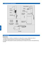
COMPONENTES PRINCIPALES Base de fijación Botón Arandela Tuerca Junta tubo del jabón Tubo jabón Depósito jabón (1000 ml) Tacos de plástico para pared Español Caja pilas INSTALACIÓN Advertencias • El dispensador no debe ser instalado en una ubicación en la que se refleje la luz del sol • No deben utilizarse productos corrosivos para la limpieza del dispensador • Se sugiere utilizar jabones sanitarios adecuados para el lavado de las manos. Evitar jabones
Open the catalog to page 4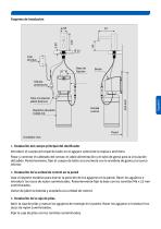
Ø 25 Caja de pilas Base de fijación Tubo circulación jabón (blanco) Unidad control 1. Instalación del cuerpo principal del dosificador Introducir el cuerpo principal de latón en el agujero central de la repisa o encimera. Pasar y conectar el cableado del sensor, el cable alimentación y el tubo de goma para la circulación del jabón. Posteriormente, fijar el cuerpo de latón a la encimera con la arandela de goma y la tuerca inferior. 2. Instalación de la unidad de control en la pared Usar el soporte metálico para marcar la posición de los agujeros en la pared. Hacer los agujeros e introducir los...
Open the catalog to page 5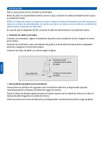
INSTALACIÓN Fijar la caja de pilas con los tornillos suministrados. Poner las pilas con la polaridad correcta, cerrar la caja y conectar los cables procedentes de la caja a la unidad de control. NOTA: La unidad de control y la caja de las pilas no deben instalarse demasiado lejos del cuerpo principal que contiene la salida de jabón, de manera que tanto los cables como el tubito de condición del jabón puedan conectarse sin dificultad. En caso de usar el adaptador AC/DC, conectar el cable de alimentación a la unidad de control. 4. Conectar los cables y los tubos. Conectar los terminales ‘negros’...
Open the catalog to page 6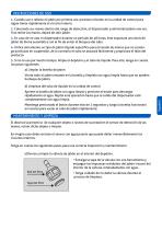
INSTRUCCIONES DE USO 1. Cuando use o rellene el jabón por primera vez, presione el botón en la unidad de control para lograr llenar rápidamente el circuito interno. 2. Colocando sus manos dentro del rango de detección, el dispensador suministrará jabón una vez. Tras retirar las manos, dejará de salir jabón. 3. En caso de no usar el dispensador durante un período de 48 horas, éste expulsará una dosis de jabón de forma automática con el fin de evitar el bloqueo del tubo. 4. Utilice únicamente un tipo de jabón líquido específico para el lavado de manos que no contenga partículas en suspensión, de...
Open the catalog to page 7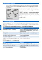
b) Compruebe si el tubo interno de circulacion del jabon liquido (blanco) esta bloqueado por jabon viscoso. En dicho caso, extraiga la junta del tubo y extraiga el jabon viscoso del tubo de jabon. Si el tubo interno de circulacion del jabon se obstruye, se recomeindan los siguientes pasos para la limpieza del mismo. 1. Extraer el tubo segun la flecha indicada en el grafico. 2. Retirar la junta del tubo y sacar el jabon viscoso del interior del tubo, presionandolo. Introducir nuevamente la junta. Se listan en la siguiente tabla los principales fallos que pueden afectar al producto y como solucio-narlos....
Open the catalog to page 8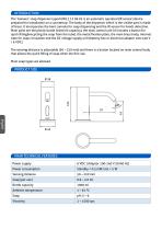
The 'Genwec' soap dispenser typed GW13 12 06 02 is an automatic operated (IR sensor) device prepared for installation on a countertop. The body of the dispenser which is the visible part is made of brass. It incorporates the bent cannula for soap dispensing and the IR sensor for hands detection. Main parts are the plastic bottle (1000 ml capacity), the main control unit (it includes a button for quick filling&recycling the soap from the tube), the metal fixation plate, the main brass body, internal tube for soap circulation and the DC voltage supply unit (battery box or electrical adaptor 100-240...
Open the catalog to page 10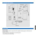
MAIN PARTS AND CONTENTS Fixation plate Button Control unit Liquid tube joint Soap tube Soap bottle (1000 ml) Plastic wall plug INSTALLATION Important issues • Do not install this product in a place where the sunlight is directly exposed or reflected to the induction window. • Do not use corrosive cleaning agents to clean the product. • Use preferably hand sanitized soap.
Open the catalog to page 11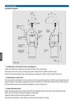
INSTALLATION Installation diagram 97 Ø 25 Battery box Fixation plate Anti-backflow device Prime button Control unit Liquid tube (white) Control unit English Wall Units: mm. 1. Installing the main body of the soap dispenser Insert the main brass body into the central hole of the countertop. Pass and connect the sensor wiring, the power cable and the rubber tube for soap. Then, fix the brass body to the countertop by screwing tne rubber wash and the lower nut. 2. Installing the control unit Put the control unit bracket on the wall and mark the positioning holes. Drill the mounting holes and push...
Open the catalog to page 12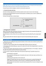
NOTE: Take care the control unit and battery box shall not to be too far away from the faucet body, otherwise the tubes and wires cannot be connected between them. In case of use an electric adaptor, connect it to the main control unit. 4. Connect the tubes and wires Connect the black plugs between the faucet and the control unit, be sure to lock the plug. Connect the red plugs between the faucet and the power unit (battery box or electric adaptor), be sure to lock the plug. Connect the soap tubes as shown below: Connect to the faucet liquid tube Connect to the white soap tube 5. Debugging after...
Open the catalog to page 13All Genwec catalogs and technical brochures
 CATALOG 4.0
198 Pages
 BATHROOM ACCESORIES BROCHURE
24 Pages
 GW13 01 06 02
1 Page
 GW13 02 06 02
1 Page
 GW13 03 06 02
1 Page
 GW13 04 06 02
1 Page
 GW13 05 06 02
1 Page
 GW13 06 06 02
1 Page
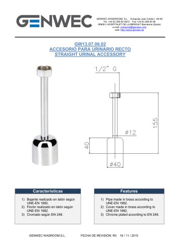
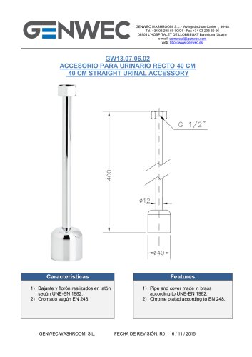 GW13 07 06 02
1 Page
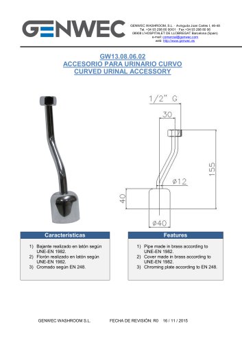 GW13 08 06 02
1 Page
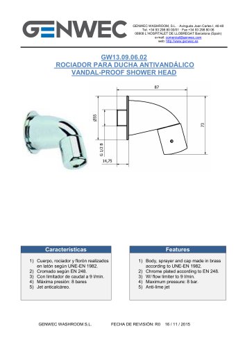 GW13 09 06 02
1 Page
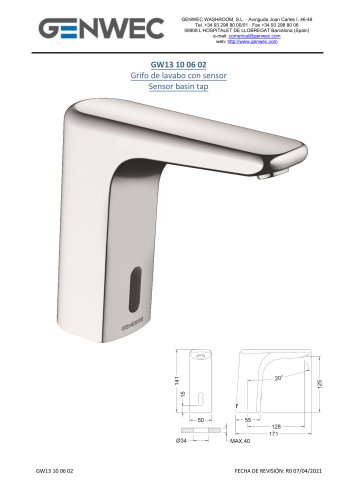 GW13 10 06 02
5 Pages
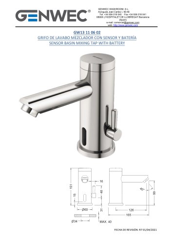 GW13 11 06 02
7 Pages
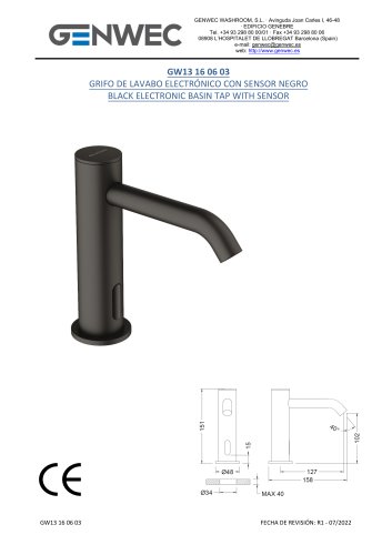 GW13 16 06 03
6 Pages
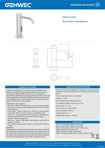 GW13 17 06 02
1 Page
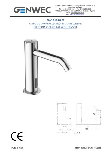 GW13 16 06 02
6 Pages
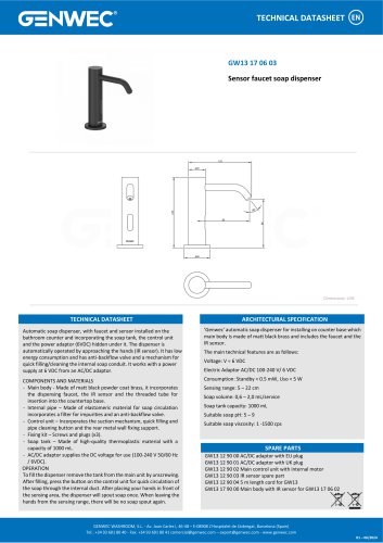 GW13 17 06 03
1 Page
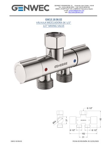 GW13 18 06 02
5 Pages
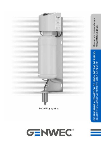 nstruction manual GW13 19 06 02
12 Pages
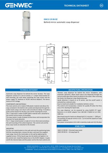 GW13 19 06 02
1 Page
 GW13 20 04 01
12 Pages
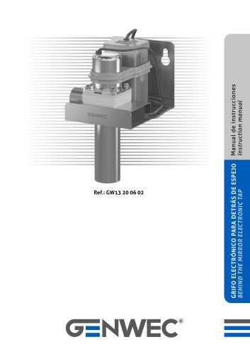 GW13 20 06 02
8 Pages
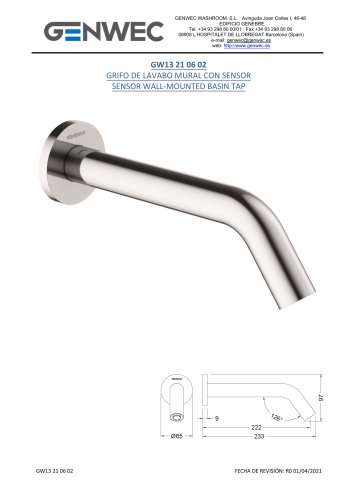 GW13 21 06 02
6 Pages
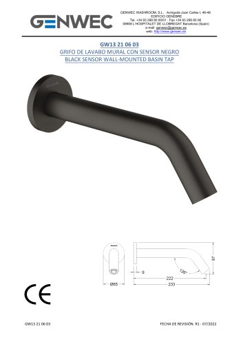 GW13 21 06 03
6 Pages
 GW12 01 04 05
8 Pages
 GW12 02 04 05
8 Pages
 GW12 02 03 05
8 Pages
 GW12 03 03 05
8 Pages
 GW12 03 04 05
8 Pages
 GW12 04 03 05
12 Pages
 GW12 04 04 05
12 Pages
 GW12 05 03 05
12 Pages
 nstruction manual GW12 05 04 05
12 Pages
 GW11 01 300mm grab bar
1 Page
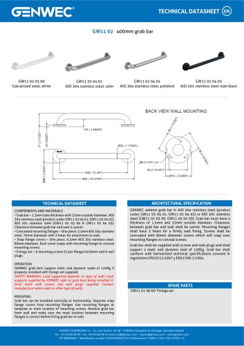 GW11 02 400mm grab bar
1 Page
 GW11 04 04 03
1 Page
 GW11 05 900mm grab bar
1 Page
 GW11 06 03 00
1 Page
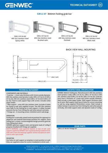 GW11 07 04 02
1 Page
 GW11 08 03 00
3 Pages
 GW11 08 04 01
3 Pages
 GW11 08 04 02
3 Pages
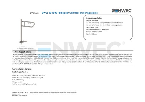 GW11 09 03 00
3 Pages
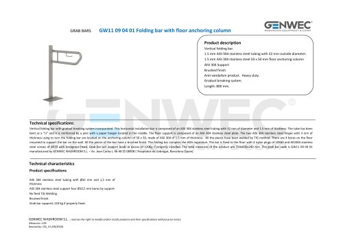 GW11 09 04 01
3 Pages
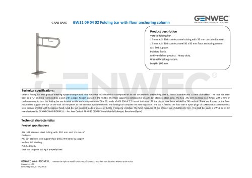 GW11 09 04 02
3 Pages
 GW11 22 04 01
2 Pages
 GW11 22 04 02
2 Pages
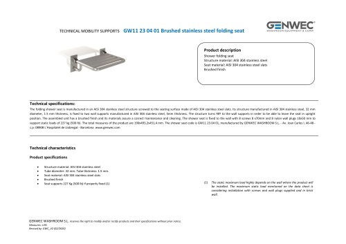 GW11 23 04 01
3 Pages
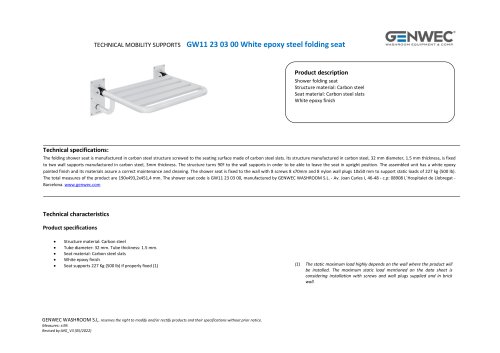 GW11 23 03 00
3 Pages
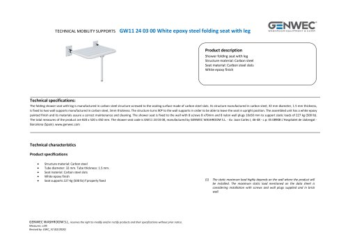 GW11 24 03 00
3 Pages
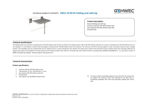 GW11 24 04 01
3 Pages
 GW11 24 11 00
3 Pages
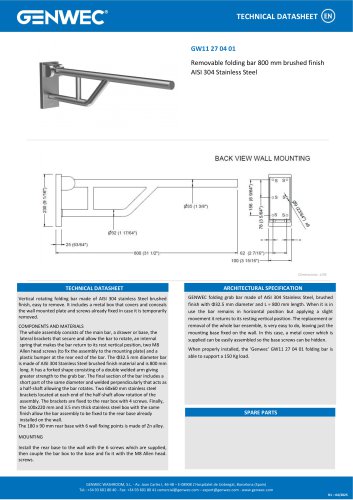 GW11 27 04 01
1 Page
 GW11 32 09 00
2 Pages
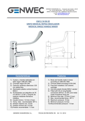 GW11 54 06 02
1 Page
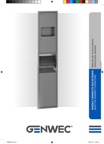 GW09 01 04 01
8 Pages
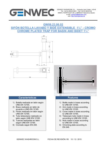 GW08 23 06 02
1 Page
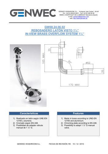 GW08 24 06 02
1 Page
 GW08 50 04 01
12 Pages
 GW08 51 04 01
12 Pages
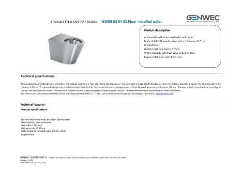 GW08 55 04 01
2 Pages
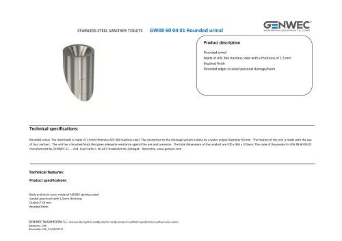 GW08 60 04 01 Rounded urinal
2 Pages
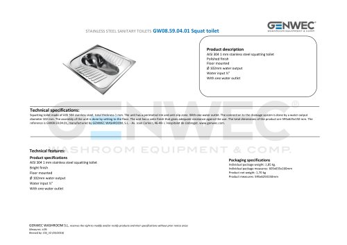 GW08.59.04.01 Squat toilet
2 Pages
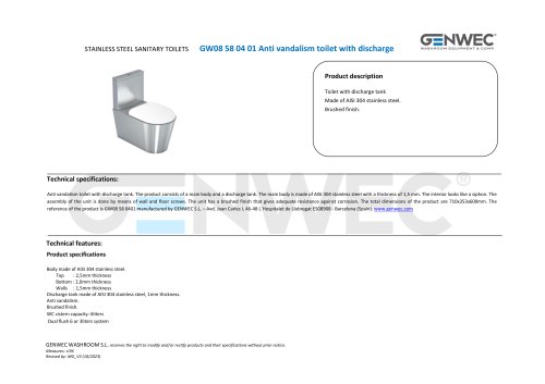 GW08 58 04 01
2 Pages
 GW07 05 04 01
1 Page
 GW07 05 01 00
1 Page
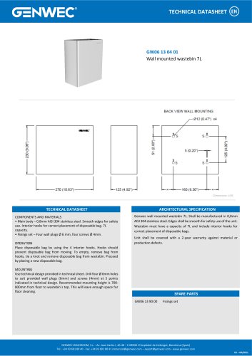 GW06 13 04 01
1 Page
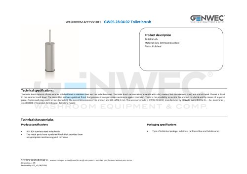 GW05 28 04 02 Toilet brush
2 Pages
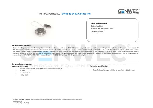 GW05 29 04 02 Clothes line
2 Pages
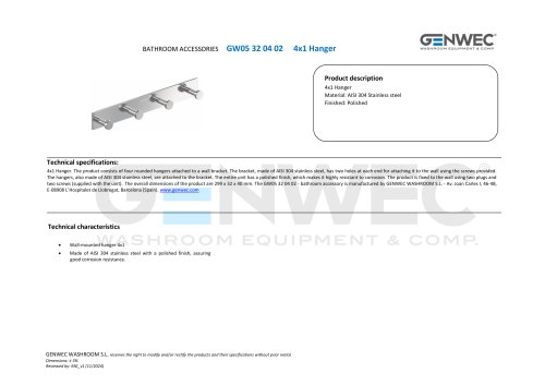 GW05 32 04 02
2 Pages
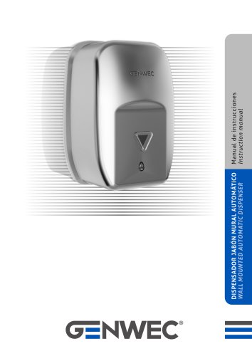 GW04 20 04 01
8 Pages
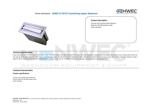 GW03 27 04 01
2 Pages
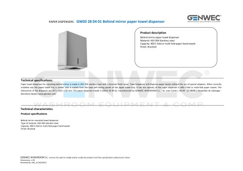 GW03 28 04 01
2 Pages
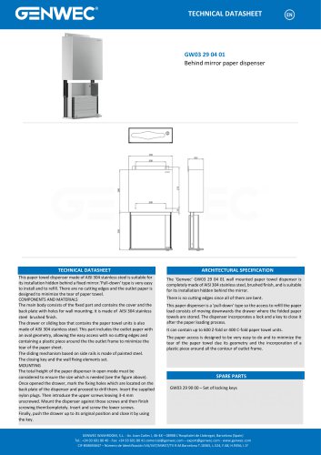 GW03 29 04 01
1 Page
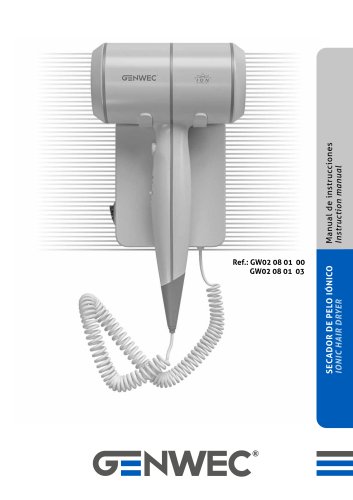 GW02 08 01 03
8 Pages
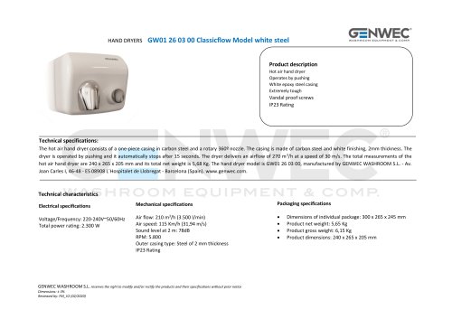 GW01 26 03 00
2 Pages
 GW01 26 04 01
2 Pages
 GW01 26 04 02
2 Pages
 GW01 17 Installation Manual
71 Pages
 GW01 16 01 00
20 Pages
 GW03 20 01 00 ABS
2 Pages
 GW03 19 01 04 ABS
2 Pages
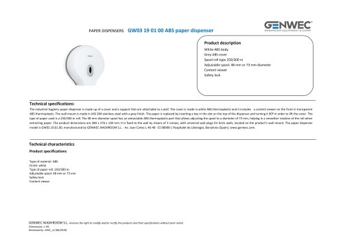 GW03 19 01 00 ABS
2 Pages
 GW03 19 01 00
2 Pages
 GW03 18 01 04
2 Pages
 GW03 18 01 00
2 Pages
 GW03 27 04 01
2 Pages
 GW03 16 04 02
2 Pages
 GW03 24 04 01
2 Pages
 GW03 04 04 02
2 Pages
 GW03 04 04 01
2 Pages
 GW03 11 04 02
2 Pages
 GW03 10 04 02
2 Pages
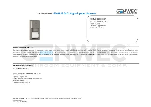 GW03 13 04 01
2 Pages
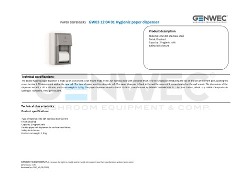 GW03 12 04 01
2 Pages
 GW03 10 04 01
2 Pages
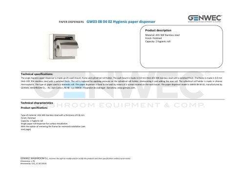 GW03 08 04 02
2 Pages
 GW03 28 04 01
2 Pages
 GW02 01 01 00 Hair dryer
1 Page
 GW01 40 FALCON series
2 Pages
 gw03 02
1 Page
 gw03 05
1 Page
 GW04 16 01 00SM
1 Page


































- Industrial tap
- Mixer faucet
- Indoor mixer tap
- Wash stand
- Contemporary wash basin
- Bathroom single-handle faucet
- Metal mixer tap
- Contemporary single-handle mixer tap
- Washbasin tap
- 1-hole single-handle faucet
- Countertop single-handle mixer tap
- Lavatory mixer tap
- Lever mixer tap
- Industrial dust-bin
- Contemporary litter bin
- Shelves
- Contemporary shelves
- Rectangular sink
- Commercial bin
- Commercial mixer tap