- Products
- Catalogs
- News & Trends
- Exhibitions
VANVEX R + / RS +
1 /52Pages
VANVEX R + / RS +
1 /52Pages
Catalog excerpts
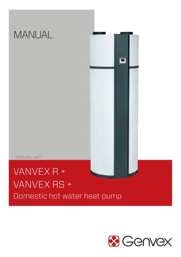
VANVEX R + VANVEX RS + Domestic hot water heat pump
Open the catalog to page 1
TABLE OF CONTENTS Introduction. . . . . . . . . . . . . . . . . . . . . . . . . . . . . . . . . . . . . . . . . . . . . . . . . . . . . . . . . . . . . . . . . . . . . 4 1. About the product. . . . . . . . . . . . . . . . . . . . . . . . . . . . . . . . . . . . . . . . . . . . . . . . . . . . . . . . . . . . . . . 4 2. Transport, Handling and Delivery. . . . . . . . . . . . . . . . . . . . . . . . . . . . . . . . . . . . . . . . . . . . . . 13 3. Positioning. . . . . . . . . . . . . . . . . . . . . . . . . . . . . . . . . . . . . . . . . . . . . . . . . . . . . . . . . . . . . . . . . . . . ....
Open the catalog to page 3
INTRODUCTION The aim of this manual is to give information, instructions and warnings on the heat pump water heater. The manual is to be used by installers and plumbers as well as by end users, since it contains important safety indications. The manual is a part of the heat pump water heater and it is to be conserved with care, since it contains important installation and maintenance instructions that can be useful to assure a long life time and an efficient operation. 1. ABOUT THE PRODUCT The product is a heat pump water heater or also domestic hot water heat pump (DHWHP) that has been designed...
Open the catalog to page 4
1.2. Technical data 1.2.1. General The heat pump water heater is composed of a water tank, a refrigerant circuit, a cabinet and a display connected to a control board. The main scope of the appliance is to heat water stored in a tank. 1.2.2. Operation The unit is programmed to start heating the water inside the tank when its temperature falls below a predetermined level. The unit stops when the water temperature reaches a set point that can be regulated by the user. In general, the appliance is designed to produce enough hot water to cover the need of a household of 4 persons or more. There are...
Open the catalog to page 5
1.2.3. Cooling circuit As depicted in Figure 1 and 2, the heat pump cycle can be divided in four main processes: compression (1-2), condensation (2-3), expansion (3-4), evaporation (4-1) described below. • At the suction of the compressor (1) the superheated gas refrigerant enters the compressor at low pressure. • In the compressor, the gas is compressed to a higher pressure and temperature level (2). • The gas is first de-superheated and condensed in the condenser, exchanging heat with water stored in the tank. • The refrigerant exits the condenser in a subcooled, liquid form (3) • Through a...
Open the catalog to page 6
Note: The extensive use of the electric heater leads to higher electricity consumption and it may lead to high electricity bills. The operation with electric heater normally consumes 3 times more electricity than the operation with heat pump. The energy released to the condenser (2-3) is, in fact, the sum between the free energy extracted from the air in the evaporator (1-4) and the energy supplied to the compressor (2-1). On average, the energy absorbed by the evaporator is more than double of the energy used to run the compressor. 1.2.4. Safety instructions – Cooling circuit • Only skilled...
Open the catalog to page 7
Refrigerant circuit GQ1: Compressor GQ2: Fan RM1: Check valve EP1:Condenser EP2: Evaporator HZ1: Filter drier QN1: Solenoid valve QN2: Thermostatic expansion valve XL3: Service valve Water circuit XL1: Water outlet XL2: Water inlet XL4*: Coil top XL5*: Coil bottom XL6: Air outlet XL7: Air inlet XL8: Condensate outlet XL9*: Hot water circulation EP3*: Coil EB1: Electric heater FR1: Anode FN1: Thermal protection Figure 4 - Design of the cooling circuit and the main components The items with * are only available for Vanvex 260 RS +.
Open the catalog to page 8
Sensors BT1: Air inlet temperature BT2: Evaporator temperature BT3: Tank water temperature BT4*: Additional temperature BT5*: Additional temperature (not included) BP1: Pressostat Electric components AA1: Main printed circuit board AA2: Display circuit board WF1: Modbus port GC1*: Solar 0-3V/10V QA1*: SG-ready port GP1*: Additional supply to pump or damper KF1*: Wi-Fi The items with * are optional. Nomenclature according to standard IEC 81346-1 and 81346-2. Figure 5 – Design of tank, condenser and related components
Open the catalog to page 9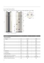
The main technical data are collected in the following figures and table. Parameter Dimensional data
Open the catalog to page 10
Electrical data Power supply Electric connections Electric heater power Cooling and water circuit Refrigerant type Refrigerant quantity Cooling circuit Hermetically sealed Protection rating Water connections - Enameled Water connections – Stainless* Water condensate connection Nominal insulation thickness Corrosion protection Magnesium anode / Stainless steel Performance data Outdoor air at 7°C (EN16147) COP Heat up time Stand-by heat losses Sound power Indoor air at 20°C (EN16147) COP Heat up time Stand-by heat losses Sound power Auxiliary power
Open the catalog to page 11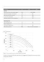
Airflow Nominal air flow rate (variable range) Max external static pressure Minimum volume of room installation Maximum fan power consumption Operating limits Max water temperature Max water pressure Figure 7 – External static pressure vs airflow at different fan speeds. In order to assure an efficient operation, it is suggested to keep the external pressure drops below 200 Pa.
Open the catalog to page 12
2. TRANSPORT, HANDLING AND DELIVERY Immediately upon receipt, the domestic hot water heater pump must be examined to make sure that it is intact and undamaged. If not, the shipping company must be informed immediately. The recipient has the responsibility for all the shipments unless otherwise agreed. The appliance is delivered without condensate drain tube and the safety equipment for the water circuit. The unit must be stored and preferably transported upright, free of water and within its packaging. Transport and storage may take place at temperatures between -10 °C and +50 °C. If the unit...
Open the catalog to page 13
2.5. Transport with Trailer The unit must only be transported on the associated transport frame. This also applies to transport on stairs. The unit must be secured against sliding on the trailer. Water connections etc. shall not be used for transportation purposes. It should be made sure that the trailer does not damage the cabinet or the various connections. Figure 8 - Transport with trailer When carefully transporting the unit over a short distance to its final location, the unit can be transported horizontally in its packaging on the dedicated side. If the unit has been tilted more than 45°,...
Open the catalog to page 14All Genvex catalogs and technical brochures
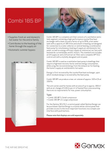 COMBI 185 BP
6 Pages
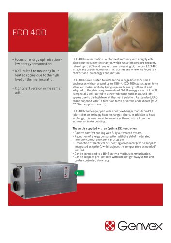 ECO 400 2022
6 Pages
 ECO 375
6 Pages
 ECO 360 R
6 Pages
 ECO 275
6 Pages
 ECO 190 XL
6 Pages
 GENVEX CONNECT
2 Pages
 ELECTRIC DUCT HEATER
2 Pages
 ELECTRIC PREHEATER
3 Pages
 GES Energy M
3 Pages
 GE Energy 2
3 Pages
 GE Energy 3
3 Pages
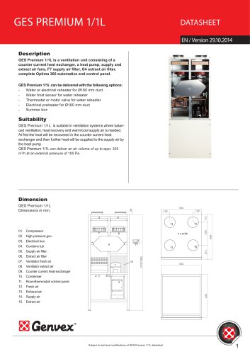 GES Premium 1/1L
4 Pages
 GE Premium 1/1L
4 Pages
 GE Premium 3
4 Pages
 Premium Preheat 250 CS/CL A
4 Pages
 Premium Preheat 300
4 Pages
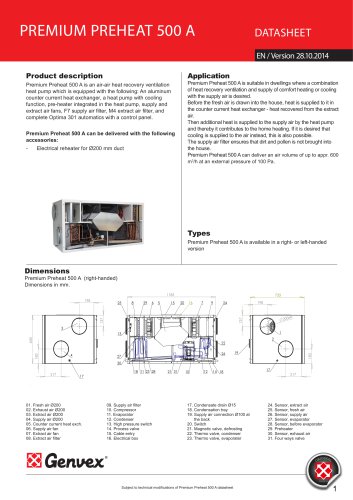 Premium Preheat 500
4 Pages
 Combi 185 S/LS opt. 311
4 Pages
 Vanvex 185/S 285/S
2 Pages
 Vanvex R
3 Pages
 Vanvex RS
3 Pages
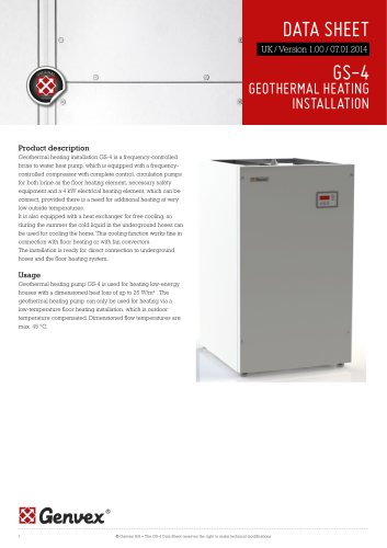 GS-4
GS-43 Pages
 Premium Preheat 250 CL P
4 Pages
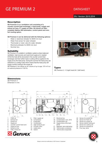 GE Premium 2
4 Pages
 GES Premium 1/1
4 Pages
 GE Energy 1
3 Pages
 GES Energy S
3 Pages
Archived catalogs
 ECO 400 2019
20 Pages
- Mechanical ventilation unit
- Ventilation controller
- Wall-mounted ventilation controller
- Ventilation unit
- Residential ventilation unit
- Home ventilation unit
- Industrial air heater
- Centralized ventilation unit
- Heat-recovery ventilation unit
- Commercial ventilation unit
- Electric air heater
- Compact ventilation unit
- Dual-flow mechanical ventilation unit
- Ventilation system control keypad
- Industrial monitoring system
- Dual-flow ventilation unit
- Wireless ventilation controller
- Class A ventilation unit
- Energy-saving ventilation unit
- Energy recovery ventilation unit