

- Products
- Catalogs
- News & Trends
- Exhibitions
ECO 400 2019
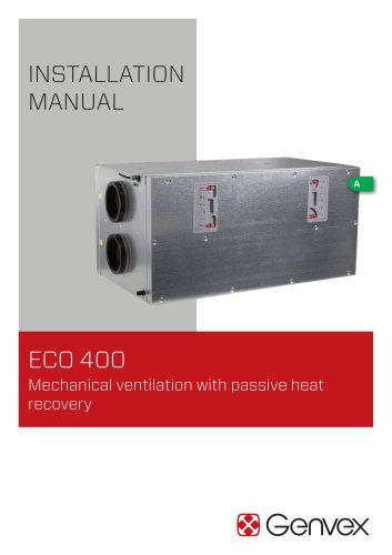
ECO 400 2019
- Filters: Replace filters when the timer indicates, avoiding vacuuming or air pressure to maintain efficiency. Filter types include G4 (Coarse), F5 (Fine), and F7 (Pollen).
- Condensate Drain: Check for blockages to prevent water damage.
- Countercurrent Heat Exchanger: Inspect and clean annually.
- Fans: Clean annually, ensuring balancing wheels are not removed.
- Supply and Extract Valves: Clean with a damp cloth without altering air settings.
- Electrical Heater: Safety thermostats disconnect if temperatures exceed limits, requiring manual re-engagement.
- System Not Running: Check for blown fuses, loose wires, or incorrect settings.
- Condensed Water Leakage: Ensure the condensate outlet is clear and protected from freezing.
- Air Faults: Issues may arise from faulty fans, clogged filters, or incorrect settings.
- Cold Supply Air: Possible causes include clogged heat exchangers or disconnected reheaters.
Catalog excerpts
ECO 400 Mechanical ventilation with passive heat recovery
Open the catalog to page 1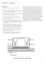
INSTALLATION IMPORTANT: Follow these instructions when you install ECO 400: 1) The machine must be mounted with an incline of 10-15mm towards the drain pipe, so that the condensed water can run freely into the outlet. 2) An airtight trap must be mounted in a frost-free place to compensate for the fan's pressure. 3) The trap height must be a minimum of 50mm. 4) It must be ensured that the drain pipe goes downwards all the way to the outlet. 5) Pour 1 litre of water into the machine's condensate tray to ensure that it runs away unobstructed. It must be checked that there is water in the trap every...
Open the catalog to page 3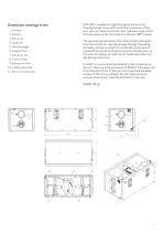
ECO 400 is supplied as right-facing (as shown in the drawing below). If you wish to flip the orientation of the unit, you can remove the front cover and back plate, mount the back plate on the front and turn the unit 180° around. 1. Fresh air 2. Exhaust 3. Extract air The unit must be placed on a firm base so that vibrations from the unit do not reproduce down through the ceiling and walls, and also so that the condensate outlet and its required trap can be led frost-free to an internal drain, as the unit can release up to 8 litres of condensed water per day during wintertime. 4. Supply air 5....
Open the catalog to page 4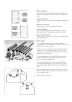
Duct connection Friskluft Incomming Air Frischluft Afkast Exhaust Air Fortluft A yellow label is affixed to all duct pipes, which indicates which ventilation ducts shall be connected to the different pipes. Supply air connected The duct system from the unit to the supply air in the living space. Exhaust air connected The duct system from the wet room to the unit. Fresh air connected The duct system from the fresh air hood/fresh air grate from outside or from the ground exchanger to the unit. Abluft Indblæsning Supply Air Return outlet connected The duct system from the unit to the exhaust hood/exhaust...
Open the catalog to page 5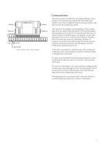
Condensate drain Lack of water in trap = water damage The units produce up to 8 litres of condensed water every 24 hours. It is therefore essential that the condensate outlet is correctly installed and the unit has an incline in the direction of the condensate outlet. The trap must be airtight, e.g. by bending a 15mm copper pipe to form a water trap (see sketch on the left) between the drainpipe on the unit (1/2" connector) and the trap can either be led to a fixed PE pipe or an adapter can be used that goes from a ½" to a 15mm hose connector. Should a hose connector be used, then remember however...
Open the catalog to page 6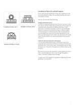
nnnnnnnnr nnnnnnnnnn/ Insulation of ducts in cold loft spaces If you wish to take advantage of the unit's high heat recovery rate (efficiency rate), it is essential that the ducts are insulated correctly. Genvex recommends the following: Supply and extract ducts In order to minimise heat loss from the duct system in cold loft spaces, the air intake ducts and exhaust ducts must be insulated with a minimum of 100mm insulation. If the alternative insulation type (A) is used, it is recommended that the insulation is carried out using 2 x 50mm slatted mats with paper or aluminium foil on the outside...
Open the catalog to page 7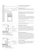
Insulation of ducts in heated spaces Genvex recommends the following: Supply and extract ducts In a warm loft space, the supply and exhaust ducts must be insulated with 50mm insulation finished with aluminium foil. Supply and extract ducts that lead into heated rooms in the building should not be insulated unless cooling, bypass or ground heating exchanger is used. In this case, the supply duct should be insulated. Fresh air and return ducts In warm loft spaces and heated rooms in the building, fresh air and return ducts should be insulated with a minimum of 50mm insulation. In addition, the...
Open the catalog to page 8
Electrical installation The electrical connection must be carried out by an authorised electrician. See the electrical diagram supplied. The cable between the unit and the control panel is a 4-wire for Optima 251, maximum 50m and an 8-wire for Optima 260, maximum 10m. Inspection and alignment of the unit In order to achieve optimal operation of the unit, it must be aligned using airflow measuring equipment. If there is a wish to run the unit prior to alignment, you can do the following before running the unit: 1. Check that the Genvex unit is mounted correctly and that all the ducts are properly...
Open the catalog to page 9
/ □□□□□□□□□ □□□□□□□□□ □□□□□□□□□ □□□□□□□□□ □□□□□□□□□ □□□□□□□□□ □□□□□□□□□J Optimal alignment of the unit In order to align a Genvex home ventilation unit, a calibrated airflow measuring device must be used. Before carrying out alignment, check that the 6 points in the section "Inspection and alignment of the unit" have been carried out. The unit can then be put into operation. It is recommended that the unit is aligned by an authorised Genvex retailer. If needed, contact Genvex on +45 7353 2700. Maintenance of the unit with control via Optima design display (combined with Optima 251 controls) A...
Open the catalog to page 10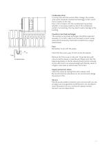
Condensate drain In connection with the autumn filter change, the condensate outlet should be checked for blockages of dirt, and if there is water in the trap. Pour 1 litre of water into the condensate tray and see whether it runs away unobstructed. If the condensate outlet is not working, this may lead to water damage in the building. Countercurrent heat exchanger The countercurrent heat exchanger should be inspected annually. If it is dirty, take it out and wash in warm, soapy water and if necessary, flush well in a bathroom, using a hand shower. Fans Remember to turn off the power. 50 100...
Open the catalog to page 11
Product number
Open the catalog to page 12
Safety thermostat in electrical heater (optional equipment) If an error occurs on an electrical heater, the safety thermostat will disconnect. The heater is equipped with a fire thermostat that automatically cuts off the power supply, if the temperature exceeds 50 °C. If the temperature decreases, the heater automatically re-engages. As an additional security there is a built-in thermal cutout, which disengages if the temperature exceeds 100 °C. Re-engaging must be done manually. Does not apply to PTC electrical heaters. The system is not running Unit stopped Possible error • Fuse in main board...
Open the catalog to page 13All Genvex catalogs and technical brochures
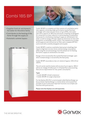 COMBI 185 BP
6 Pages
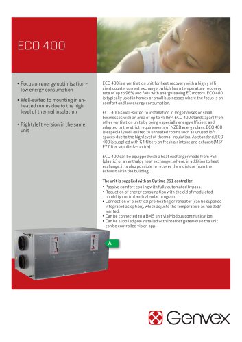 ECO 400 2022
6 Pages
 ECO 375
6 Pages
 ECO 360 R
6 Pages
 ECO 275
6 Pages
 ECO 190 XL
6 Pages
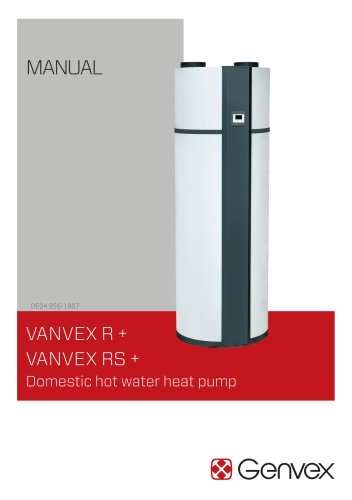 VANVEX R + / RS +
52 Pages
 GENVEX CONNECT
2 Pages
 ELECTRIC DUCT HEATER
2 Pages
 ELECTRIC PREHEATER
3 Pages
 GES Energy M
3 Pages
 GE Energy 2
3 Pages
 GE Energy 3
3 Pages
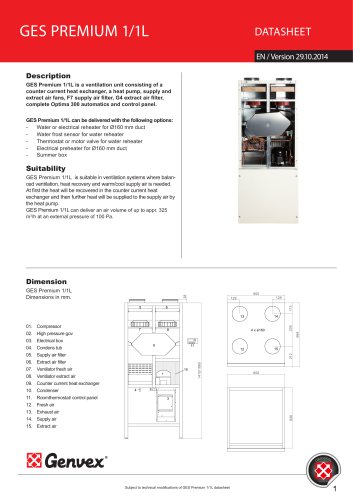 GES Premium 1/1L
4 Pages
 GE Premium 1/1L
4 Pages
 GE Premium 3
4 Pages
 Premium Preheat 250 CS/CL A
4 Pages
 Premium Preheat 300
4 Pages
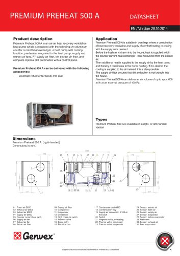 Premium Preheat 500
4 Pages
 Combi 185 S/LS opt. 311
4 Pages
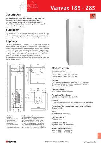 Vanvex 185/S 285/S
2 Pages
 Vanvex R
3 Pages
 Vanvex RS
3 Pages
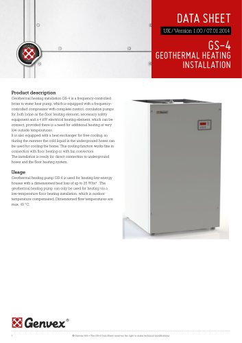 GS-4
GS-43 Pages
 Premium Preheat 250 CL P
4 Pages
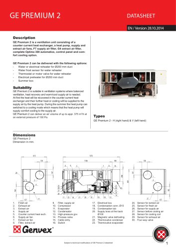 GE Premium 2
4 Pages
 GES Premium 1/1
4 Pages
 GE Energy 1
3 Pages
 GES Energy S
3 Pages
- Mechanical ventilation unit
- Ventilation controller
- Wall-mounted ventilation controller
- Residential ventilation unit
- Industrial air heater
- Home ventilation unit
- Centralized ventilation unit
- Heat-recovery ventilation unit
- Commercial ventilation unit
- Electric air heater
- Compact ventilation unit
- Dual-flow mechanical ventilation unit
- Ventilation system control keypad
- Industrial monitoring system
- Dual-flow ventilation unit
- Class A ventilation unit
- Wireless ventilation controller
- Energy-saving ventilation unit
- Energy recovery ventilation unit