INSTRUCTION HUB
1 /36Pages
INSTRUCTION HUB
1 /36Pages
Catalog excerpts

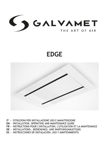
IT - ISTRUZIONI PER INSTALLAZIONE USO E MANUTENZIONE EN - INSTALLATION, OPERATING AND MAINTENANCE GUIDE FR - INSTRUCTIONS POUR L'INSTALLATION, L'UTILISATION ET LA MAINTENANCE DE - ANWEISUNGEN FÜR INSTALLATION, GEBRAUCH UND WARTUNG ES - INSTRUCCIONES DE INSTALACIÓN, USO Y MANTENIMIENTO
Open the catalog to page 1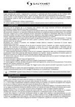
Cappa aspirante per cucina. L’apparecchio è costruito in conformità alle Norme Europee ed alle richieste delle Direttive: 2006/95 CEE (Sicurezza elettrica - Bassa tensione), 2004/108 CEE (Compatibilità elettromagnetica). Questo libretto è parte integrante della cappa e di conseguenza deve essere conservato con cura e deve SEMPRE accompagnarla, anche in caso di sua cessione ad altro proprietario o utente, oppure di trasferimento su un’altra installazione. Il produttore si impegna per continui miglioramenti. Per questa ragione, il testo e le illustrazioni in questo manuale possono essere cambiati...
Open the catalog to page 5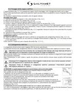
III.2 Fissaggio della cappa a soffitto L’apparecchiatura (Fig. 3.2.1) e composta da cappa e funi di ancoraggio, tutti i fissaggi sono forniti con la cappa. Per il corretto posizionamento della parte aspirante rispetto al piano cottura considerare le misure d’ingombro riportate in Fig. 3.2.2. Per installare l’apparecchiatura procedere come di seguito indicato: Montaggio della cappa 1) Tracciare il soffitto ed eseguire i 4 fori come illustrato in Fig. 3.2.3. 2) Bloccare le boccole con viti e tasselli (Fig. 3.2.4-A). 3) Infilare la fune metallica sull’apposito supporto (Fig. 3.2.4-B). 4) Avvitare...
Open the catalog to page 6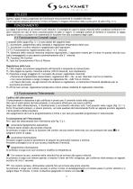
Questa cappa è stata progettata per funzionare esclusivamente in modalità filtrante. I fumi aspirati passano attraverso il filtro al Plasma e vengono reimmessi nella cucina privi di odori (Fig. 4.1). La cappa è provvista di un motore a più velocità. Si consiglia di usare la bassa velocità nelle condizioni ordinarie e le altre velocità nei casi di forte concentrazione di odori e vapori. Si consiglia inoltre di mettere in funzione la cappa quando si inizia a cucinare e di mantenerla in funzione fino alla scomparsa degli odori. V.1 Funzionamento Comandi cappa I comandi nella cappa (Fig. 5.1.1) sono...
Open the catalog to page 7
V.3 Attivazione Autospegnimento Ritardato Regolabile Questa funzione permette di impostare lo spegnimento ritardato del prodotto dopo la fine della fase di cottura, in modo tale che venga ripristinato, nel più breve tempo possibile, il giusto livello di purezza dell’aria della vostra cucina. Con la cappa in funzione, scegliere la velocità desiderata, quindi tenere premuto il tasto T2+T3 per alcuni secondi fino a quanto tutti i led cominciano a lampeggiare (T1,T2,T3,T4). Premendo uno dei tasti (T1,T2,T3,T4) si può programmare il tempo di autospegnimento, secondo quanto segue: T1 uguale a 5 minuti;...
Open the catalog to page 8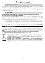
VI.2 Filtro antiodore al Plasma Il filtro anti odore al Plasma non richiede particolare manutenzione e la sua durata è di circa 10 anni mantenendo invariata la sua efficienza nell’eliminare gli odori, virus e batteri presenti nell’aria. Il corretto funzionamento del filtro al Plasma è indicato dall’accensione della spia led (Fig. 5.1.1-PL) di colore verde presente nei comandi della cappa. Il filtro entra in funzione automaticamente al passaggio dell’aria. La spia led (Fig. 5.1.1-PL) risulta quindi sempre accesa con l’aspiratore in funzione, questo significa il corretto funzionamento del filtro...
Open the catalog to page 9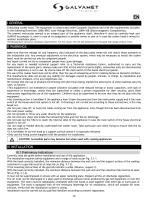
EN I GENERAL Exhausting cooker hood. The equipment is constructed under European Standards and with the requirements included in the following Directives: 2006/95EC (Low Voltage Directive), 2004/108 (Electromagnetic Compatibility). The present instruction manual is an integral part of the appliance itself, therefore it must be carefully kept and ALWAYS accompany it, even in case of its assignment to another owner or user or in case the cooker hood is moved to another installation plant. The Manufacturer strives for continuous improvements. For this reason, the text and illustrations in this guide...
Open the catalog to page 10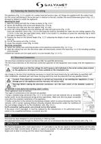
III.2 Fastening the hood to the ceiling The appliance (Fig. 3.2.1) consists of a cooker hood and anchor ropes, all fixings are supplied with the cooker hood. For the correct positioning of the suction part in relation to the hob, consider the overall dimensions given in Fig. 3.2.2. Proceed as follows to install the appliance: 1) Mark the ceiling and drill the 4 holes as shown in Fig. 3.2.3. 2) Secure the bushings with screws and dowels (Fig. 3.2.4-A). 3) Thread the wire rope onto the wire support (Fig. 3.2.4-B). 4) Screw the ceiling supports onto the bushings and close the grub screw (Fig. 3.2.5)....
Open the catalog to page 11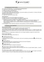
V.1 Operating the hood controls The controls on the hood (Fig. 5.1.1) are fitted with the following buttons: TL: Lamp switch on/off and light temperature adjustment. T1: Switch-on at speed 1 and extractor off. T2-T3: Operation at speeds 2 and 3 respectively. T4: Intensive speed setting (maximum extraction), the extractor operates at this speed for 5 minutes (with button flashing) and then automatically switches speed 3. TR: 24-hour Comfort function PL: Plasma filter operation LED indicator light Light adjustment: TL single click: on/off at the stored brightness and temperature. TL double click...
Open the catalog to page 12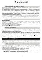
V.3 Adjustable Delayed Auto Power-Off Activation This feature allows a delayed power-off after the end of the cooking phase so that the right level of air purity in your kitchen is restored as quickly as possible. With the hood in operation, choose the desired speed, then press and hold the T2+T3 button for a few seconds until all the LEDs start to flash (T1, T2, T3, T4). By pressing one of the buttons (T1,T2,T3,T4), the auto power-off time can be programmed, as follows: T1 for 5 minutes; T2 for 10 minutes; T3 for 15 minutes; T4 for 20 minutes During auto power-off operation, the set speed (including...
Open the catalog to page 13
VI.2 Plasma anti-odour filter The Plasma anti-odour filter does not require any special maintenance and its lifetime is approximately 10 years, maintaining its efficiency in eliminating odours, viruses and bacteria in the air. Correct operation of the Plasma filter is indicated by a green LED indicator light (Fig. 5.1.1-PL) on the hood controls. The filter is automatically activated when air flows through it. The LED indicator light (Fig. 5.1.1-PL) is therefore always switched on when the extractor is in operation, which means that the filter itself is operating correctly. VI.3 Hood Cleaning...
Open the catalog to page 14All Galvamet catalogs and technical brochures
 INSTRUCTIONS EDGE
16 Pages
 INSTRUCTIONS GLOBE
20 Pages
 INSTRUCTIONS SLIVER
24 Pages
 INSTRUCTIONS OPERA
20 Pages
- Extractor hood
- Range hood with built-in lighting
- Wall-mounted cooker hood
- Ducted range hood
- Black range hood
- Island range hood
- Gray range hood
- Class A range hood
- Ductless range hood
- Low-noise range hood
- Built-in range hood
- White range hood
- Original design range hood
- Ceiling-mounted range hood
- Range hood with touchscreen
- Remote-controlled range hood
- Class B range hood
- Class C range hood
- Activated carbon range hood
- Class D range hood