


- Company
- Products
- Catalogs
- News & Trends
- Exhibitions
CLADDING TECHNICAL CATALOGUE
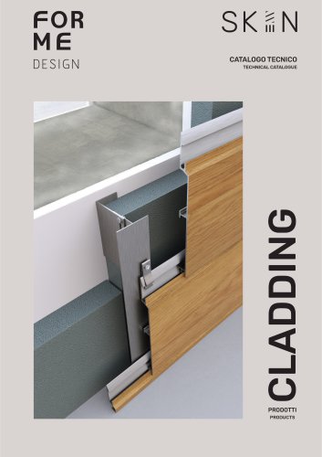
CLADDING TECHNICAL CATALOGUE
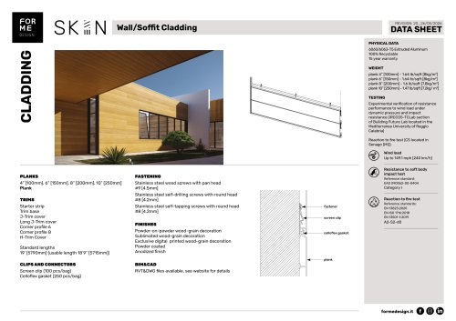
The CLADDING aluminium system is designed for architectural applications both indoors and outdoors. It is suitable for wall covering and redevelopment, offering a modern alternative to traditional wood matchboards with various decorative options. The system includes profiles with visible surfaces of 150, 200, or 250 mm, and elements for linear, corner, and finishing joints.
The system is constructed from extruded aluminium alloy EN AW-6060/6063, adhering to UNI EN 573-3 and UNI EN 515 standards. Installation is facilitated by a snap coupling with a steel clip, allowing for expansion. Foam gaskets are placed between slats, and all raw aluminium surfaces are protected with neutral sealants. Only original accessories certified by Forme should be used to maintain certification validity.
The profiles are resistant to dynamic wind loads up to 240 km/h and soft body impact (Category I). Fire behaviour is classified as A2 with smoke production S2 and no flaming droplets (d0). The aluminium undergoes a SEASIDE pretreatment for enhanced corrosion resistance, followed by an electrostatic coating process compliant with QUALICOAT and QUALIDECO standards.
The document details various profiles and accessories, including plank sizes ranging from 100 mm to 250 mm, corner profiles, and wall holders. Each component is described with dimensions to ensure compatibility and proper installation.
Technical drawings provide detailed installation guidance, including horizontal installation configurations and weight per square foot for different plank sizes. These drawings ensure precise assembly and adherence to specifications.
Catalog excerpts
TECHNICAL CATALOGUE CLADDING PRODOTTI
Open the catalog to page 1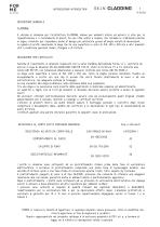
DESCRIZIONE GENERALE CLADDING: Il sistema in alluminio per l'architettura CLADDING, idoneo per ambienti interni ed esterni, e utile per la riqualificazione o il rivestimento di pareti, ha uno stile sobrio e lineare, che richiama le tradizionali perline in legno, rivisitato per rispondere anche al design piu sofisticato grazie all'ampia varieta di decorazioni. La gamma di profili comprende la doga che ha una superficie in vista di 150, 200 o 250 mm e altri elementi utili a realizzare giunzioni lineari, d'angolo e di finitura. Sistema di rivestimento in alluminio realizzato con la serie Cladding...
Open the catalog to page 2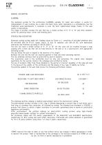
INTRODUZIONE-INTRODUCTION SKSiN CLADDING 3 GENERAL DESCRIPTION CLADDING: The aluminium system for the architecture CLADDING, suitable for indoor and outdoor, is useful for redevelopment or wall covering, has a sober and linear style, which reproduces in a contemporary key the traditional wood matchboards. It responds to even the most sophisticated design thanks to the wide variety of decorations. The range of profiles includes the slat that has a visible surface of 6”, 8” or 10” and other elements useful for achieving linear, corner and finishing joints. SPECIFICATION DESCRIPTION Aluminium coating...
Open the catalog to page 3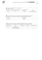
RAPPORTI DI PROVA-TEST REPORTS /3\ Prova di resistenza al vento sotto pressioni dinamiche vry Dynamic wind load test fjb) Prova di resistenza all'urto da corpo mode (Norma di riferimento: EAD 090062-00-04-04- AUegato G) Resistance to soft body impact test (Reference standard: EAD 090062-00-0U0U Annex G) Prova di reazione al fuoco (Norme di riferimento EN 13823:2020, EN ISO 1716:2018, EN 13501-1:2019) Reaction to fire test (Reference standards: EN 13823:2020, EN ISO 1716:2018, EN 13501-1:2019)
Open the catalog to page 4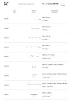
ELENCO PROFILI-PROFILES LIST CODICE PROFILO DESCRIZIONE code profile description PROFILO DI PARTENZA Starter strip PROFILO COMPENSAZIONE TERMINALE Trim base COVER COMPENSAZIONE TERMINALE 30 mm J-trim cover COVER COMPENSAZIONE TERMINALE 80 mm Long j-trim cover GIUNTO LINEARE H-trim cover
Open the catalog to page 5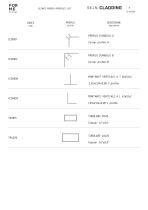
ELENCO PROFILI-PROFILES LIST CODICE PROFILO DESCRIZIONE code profile description PROFILO D'ANGOLO A Corner profile A PROFILO D'ANGOLO B Corner profile B MONTANTE VERTICALE A T 60x52x2 2,36x2,04x0,08 T profile MONTANTE VERTICALE A L 42x52x2 1,65x2,04x0,08 L profile
Open the catalog to page 6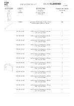
ELENCO ACCESSORI-TOOLS LIST CODICE code DESCRIZIONI description clip acciaio cladding screen clip FA30005 guarnizione celloflex diam. 4,8 mm x 50 mm 250 ATK 100 LSH 60 staffa a muro di trattenimento L=60 mm 1 ATK 100 LSH 80 staffa a muro di trattenimento L=80 mm 1 ATK 100 LSH 100 staffa a muro di trattenimento L=100 mm 1 ATK 100 LSH 120 staffa a muro di trattenimento L=120 mm 1 ATK 100 LSH 140 staffa a muro di trattenimento L=140 mm 1 ATK 100 LSH 160 staffa a muro di trattenimento L=160 mm 1 ATK 100 LSH 180 staffa a muro di trattenimento L=180 mm 1 ATK 100 LSH 200 staffa a muro di trattenimento...
Open the catalog to page 7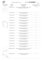
ELENCO ACCESSORI-TOOLS LIST SKisN CLADDING « 02.07.2026 THERMOSTOP 80 LSH elemento compensazione dilatazione termica L=80 mm 1 thermal separation element L=3,15" ATK 100 LFH 60 staffa a muro portante L=60 mm ATK 100 LFH 80 staffa a muro portante L=80 mm ATK 100 LFH 100 staffa a muro portante L=100 mm ATK 100 LFH 120 staffa a muro portante L=120 mm ATK 100 LFH 140 staffa a muro portante L=140 mm ATK 100 LFH 160 staffa a muro portante L=160 mm ATK 100 LFH 180 staffa a muro portante L=180 mm ATK 100 LFH 200 staffa a muro portante L=200 mm ATK 100 LFH 220 staffa a muro portante L=220 mm ATK 100 LFH...
Open the catalog to page 8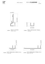
PROFILO COMPENSAZIONE TERMINALE Trim base COVER COMPENSAZIONE TERMINALE 30 mm J-trim cover PROFILO DI PARTENZA Starter strip 80 [3,150"] COVER COMPENSAZIONE TERMINALE 80 mm CC00007 Long j-trim cover
Open the catalog to page 11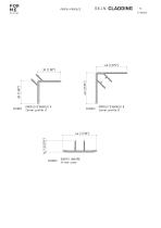
PROFILO D'ANGOLO A Corner profile A GIUNTO LINEARE H-trim cover PROFILO D'ANGOLO B Corner profile B
Open the catalog to page 12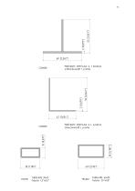
MONTANTE VERTICALE A T 60x52x2 2,36x2,04x0,08 T profile 42 [1,654"] MONTANTE VERTICALE A L 42x52x2 1,65x2,04x0,08 L profile
Open the catalog to page 13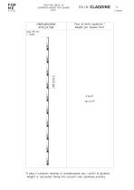
PESO PER UNITA' DI SUPERFICIE-WEIGHT PER SQUARE FOOT CONFIGURAZIONE Peso al metro quadrato * APPLICATION Weight per Square Foot Il peso e calcolato tenendo in considerazione solo i profili di alluminio. Weight is calculated taking into account only aluminium profiles.
Open the catalog to page 14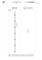
PESO PER UNITA' DI SUPERFICIE-WEIGHT PER SQUARE FOOT CONFIGURAZIONE Peso al metro quadrato * APPLICATION Weight per Square Foot Il peso e calcolato tenendo in considerazione solo i profili di alluminio. Weight is calculated taking into account only aluminium profiles.
Open the catalog to page 15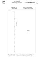
PESO PER UNITA' DI SUPERFICIE-WEIGHT PER SQUARE FOOT CONFIGURAZIONE Peso al metro quadrato * APPLICATION Weight per Square Foot Il peso e calcolato tenendo in considerazione solo i profili di alluminio. Weight is calculated taking into account only aluminium profiles.
Open the catalog to page 16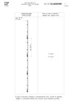
PESO PER UNITA' DI SUPERFICIE-WEIGHT PER SQUARE FOOT CONFIGURAZIONE Peso al metro quadrato * APPLICATION Weight per Square Foot Il peso e calcolato tenendo in considerazione solo i profili di alluminio. Weight is calculated taking into account only aluminium profiles.
Open the catalog to page 17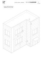
SEZIONI-TECHNICAL DRAWINGS INSTALLAZIONE ORIZZONTALE HORIZONTAL INSTALLATION
Open the catalog to page 18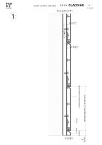
DESIGN SEZIONI-TECHNICAL DRAWINGS
Open the catalog to page 19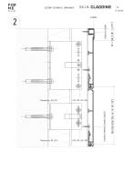
SEZIONI-TECHNICAL DRAWINGS
Open the catalog to page 22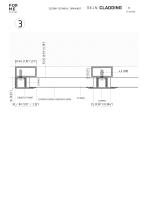
SEZIONI-TECHNICAL DRAWINGS
Open the catalog to page 23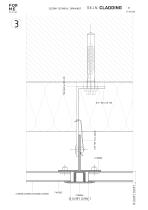
SEZIONI-TECHNICAL DRAWINGS
Open the catalog to page 24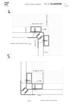
SEZIONI-TECHNICAL DRAWINGS
Open the catalog to page 25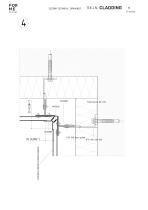
SEZIONI-TECHNICAL DRAWINGS
Open the catalog to page 26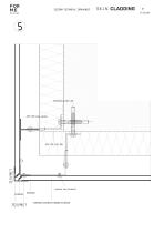
SEZIONI-TECHNICAL DRAWINGS custom inox bracket CC00004
Open the catalog to page 27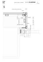
SEZIONI-TECHNICAL DRAWINGS
Open the catalog to page 28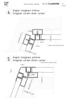
SEZIONI-TECHNICAL DRAWINGS Angolo irregolare interno Irregular corner-Inner corner Angolo irregolare esterno Irregular corner-Outer corner
Open the catalog to page 29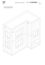
SEZIONI-TECHNICAL DRAWINGS INSTALLAZIONE VERTICALE VERTICAL INSTALLATION
Open the catalog to page 30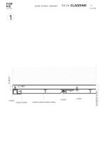
SEZIONI-TECHNICAL DRAWINGS
Open the catalog to page 31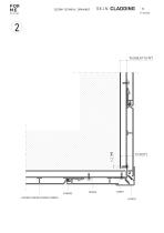
SEZIONI-TECHNICAL DRAWINGS
Open the catalog to page 32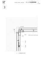
SEZIONI-TECHNICAL DRAWINGS
Open the catalog to page 33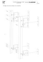
ISTRUZIONI DI MONTAGGIO-ASSEMBLY SKSN CLADDING INSTRUCTIONS Montaggio sottostruttura (Substructure installation)
Open the catalog to page 34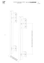
ISTRUZIONI DI MONTAGGIO-ASSEMBLY INSTRUCTIONS 800 mm massima distanza (32" maximum distance)
Open the catalog to page 35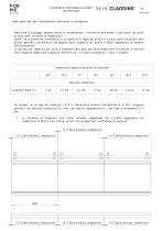
ISTRUZIONI DI MONTAGGIO-ASSEMBLY INSTRUCTIONS Note important per l'installazione: dilatazione e contrazione Nella fase di montaggio bisogna tenere in considerazione i fenomeni di dilatazione e contrazione dei profili a causa della variazione di temperatura. Quindi, tra la parete del rivestimento e la superficie di taglio del profilo e tra due profili consecutivi deve essere garantita una distanza che dipende dalla lunghezza del profilo e dalla temperatura al momento dell'installazione. La distanza da rispettare per unita di lunghezza della doga alle varie temperature di esercizio e riportata...
Open the catalog to page 36All ForMe catalogs and technical brochures
 Skin Brochure
60 Pages
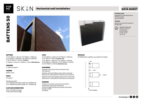
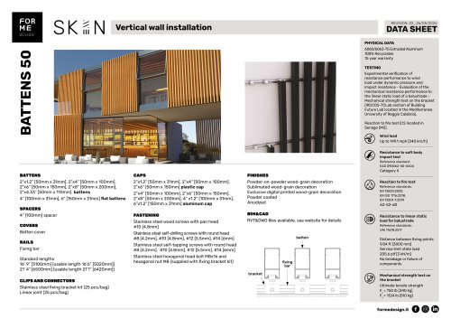
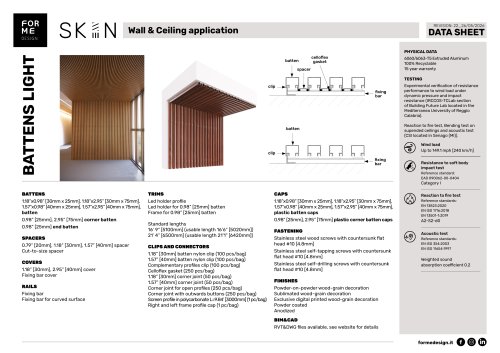
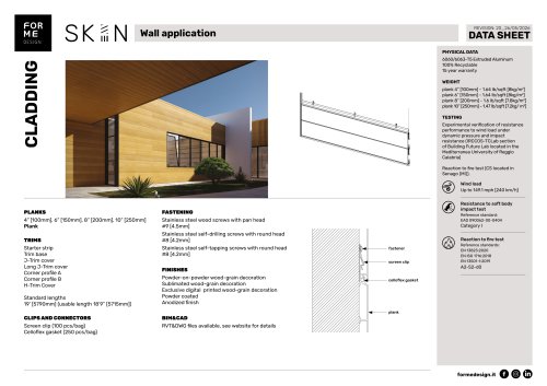 Data Sheet Wall application
3 Pages
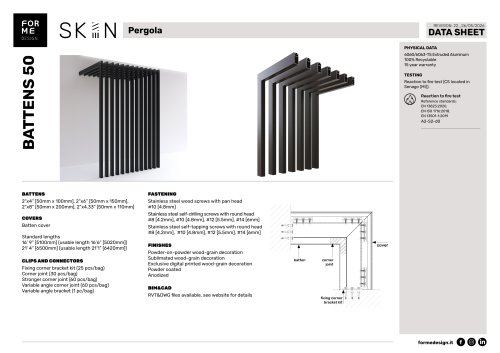 Data Sheet Pergola
4 Pages
 SHADING TECHNICAL CATALOGUE
100 Pages
 Suspended ceiling
5 Pages
Archived catalogs

- Industrial wallcovering
- Interior wall-covering
- Domestic use wall-covering
- Panel rainscreen cladding
- Commercial wall-covering
- Decorative wall-covering
- Modern wall-covering
- Industrial suspended ceiling
- Metal cladding
- Textured wall-covering
- Fire-retardant wall-covering
- Living room wall-covering
- Decorative cassetta
- Indoor ceiling
- Wall cladding panel
- Industrial solar shading
- Washable wall-covering
- Facade solar shading
- Sustainable rainscreen cladding