- Catalogs
- Fischer Profil GmbH
- FischerKLIPTEC - standing seam roofs
FischerKLIPTEC - standing seam roofs

FischerKLIPTEC - standing seam roofs
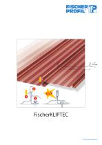
FischerKLIPTEC is an innovative roofing system by Fischer Profil, part of Tata Steel, designed for quick and easy assembly. It simplifies traditional standing seam roofs by using a single building element, eliminating the need for additional accessories.
Specifications
The panels are prefabricated with a registered design, requiring no drilled holes or special tools for installation. They comply with DIN EN 505 standards and can be used with or without insulation, suitable for various roof pitches and constructions.
Assembly Procedure
Installation involves modular division of the roof area. The first panel is secured with self-sealing screws, and subsequent panels interlock. The system is designed to withstand wind loads due to its strong longitudinal joints.
Material and Coatings
Available in materials like aluzinc, stainless steel, aluminium, and copper, FischerKLIPTEC features corrosion protection systems such as Colorcoat HPS 200 and Prisma, ensuring weather resistance and durability.
Applications
Suitable for single-skin and multi-skin roofs, the system is ideal for new constructions or renovations, especially effective for flat-sloped roofs with excellent corrosion protection.
Load and Fastening Details
Includes detailed load tables and permissible load values for different support spans and sheet thicknesses, along with suitable screws and fastening methods for various substrates.
Thermal Considerations
Addresses thermal bridges due to metallic fasteners, providing guidelines to maintain insulation effectiveness and references standards for calculating heat transfer coefficients.
Conclusion
FischerKLIPTEC provides a simple, efficient, and durable roofing solution, emphasizing ease of installation and long-term performance, supported by comprehensive technical specifications and guidelines.
Catalog excerpts
* A Tata Steel Enterprise
Open the catalog to page 1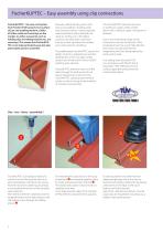
FischerKLIPTEC – Easy assembly using clip connections FischerKLIPTEC - the new roof system from Fischer Profil consists in its surface of just one building element. Unlike all other metal roof coverings on the market, no other accessories such as holding clips or holding brackets etc. are necessary. This means that FischerKLIPTEC is not only particularly easy but also particularly quick to assemble. Manually crafted standing seam roofs have a long tradition. Standing seam roofs were and still are mainly employed where particularly heavy demands are made on roofing, e.g. in the Alpine countries....
Open the catalog to page 2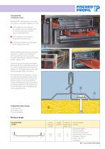
FischerKLIPTEC a multitude of uses. FischerKLIPTEC roof elements can be used to a minimum roof pitch of approx. 3° or 5 %. As the upper skin of a single-skin non-aerated roof (non-insulated roof ) on various bearing constructions, such as trapezoidal sheets. As the upper skin of a multi-skin aerated roof (insulated roof ). As a renovating element for damaged roofs of almost every kind. Fischer standing seam elements are manufactured on a modern new profiling line which guarantees continuous quality. For ease of handling, the maximum element length is approx. 16 m. Due to the process of cutting...
Open the catalog to page 3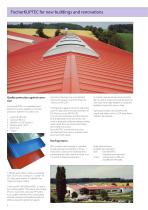
FischerKLIPTEC for new buildings and renovations Quality protection against corrosion As FischerKLIPTEC is a weathered roof element, it is only supplied in corrosion protection systems for outdoor use: 1. Colorcoat HPS 200 2. Colorcoat Prisma 3. 55%AlZn AZ 185 (aluzinc) 4. Stainless steel 1.4301 5. Aluminium 6. Copper mechanical damage. For more detailed information please consult the brochure “Colorcoat HPS 200“. The protection against corrosion with Colorcoat HPS 200 Ultra, Prisma and 55%AlZn AZ 185 (Aluzinc) as per DIN 55 634. This corrosion protection and the absence of all drilled holes...
Open the catalog to page 4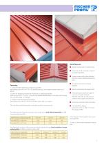
Main features Metallic roofing with no drilled holes. Extremely simple assembly in almost any kind of weather. System consists of just one building element without additional fastening parts. No special tools of any kind are required. Fastening 1. Screws for direct fastening to distancing profiles: self-sealing screw JA3 -6.5 x 19 -E16, stainless steel, (≤ 2 mm sheet thickness) order no. FI 90.053 2.Screws for fastening through hard insulation in trapezoidal profiles: drilling screw JT3 -2 -X -6.0 x L -E16, with saw thread, stainless steel, (L=thickness of the insulation +20 mm) order no. Fl...
Open the catalog to page 5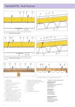
FischerKLIPTEC - Roof Structure 6 As the upper skin of a multi-skin roof with trapezoidal profiles beneath on hard thermal insulation As the upper skin of a multi-skin roof with trapezoidal profiles beneath on soft thermal insulation with distancing profi les under 45° 14 As renovating element on corrugated cement boards On timber frame with bitumen sheet 1 FischerKLIPTEC 2 FischerTRAPEZ 3 Drilling screw JT3-2-X-6,0 x L-E16 4 Powder actuated fastener Hilti EN P2-21-L15 5 Hard mineral fibre insulation 6 Vapour barrier 7 Z-profile Aluzinc, t =1.50 mm laid to trapezoidal profile under...
Open the catalog to page 6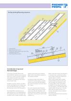
1 FischerKLIPTEC 2 Bulb-tite butt rivet 5.2 x 19.1 3 Permanently elastic sealing strip, single-sided, self-adhesive, illac 20 x 2 4 Hard mineral fibre insulation Consideration of punctual thermal bridges In the area of metallic fasteners for FischerKLIPTEC elements, punctual heat losses occur which must be considered when determining the heat transfer coefficient U according to the Energy Conservation Code. At RWTH university, Aachen, the effect of thermal bridges due to metallic fasteners was determined by way of threedimensional numeric FEM calculations. If FischerKLIPTEC roof elements are...
Open the catalog to page 7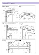
FischerKLIPTEC – Details Industrial Guttering 11 Verge Flashing (Attica)/Gable Verge Type 5 Laying direction
Open the catalog to page 8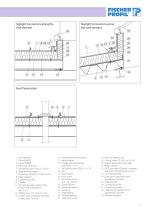
Skylight Connectors along the roof element Skylight Connectors across 6 Verge flashing support 18 7 Polystyrene board min. 20 mm thick 19 11 Permanently elastic sealing strip 22 13 Condensation protection sheeting 26 in eaves area 3 m wide 27 Hard mineral fibre insulation 28 Powder actuated fastener 30 Self-sealing screw Edge flashing Polyethylene infill Bend up valley on site Ridge capping for mono-ridge Ridge capping EJOT pipe sleeve"Dektite" complete with Color Drill JCD drilling screw Connecting profile Load-bearing skylight frame Ridge skylight Connecting profile Connecting bracket Load-bearing...
Open the catalog to page 9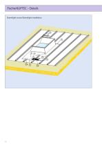
FischerKLIPTEC – Details Domelight crown/Domelight installation
Open the catalog to page 10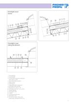
Domelight crown (eaves) Domelight crown (along the element) 1 FischerKLIPTEC 2 FischerTRAPEZ 3 Condensation protection sheeting in eaves area 3 m wide 4 Hard mineral fibre insulation 5 Vapour barrier 6 Timber beam 7 Trapezoidal profile header joist 8 Domelight binding profile 9 Bulb-tite butt rivet 5.2 x 19.1 10 Self-sealing screw JA3 – 6.5 x 64-E16 11 Toothed flashing 12 Polyethylene infill 13 Z-profile 14 Countersunk head screw 15 Domelight crown 16 Permanently elastic sealing strip single-sided, self-adhesive illac 20 x 2 11
Open the catalog to page 11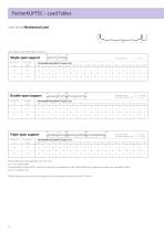
FischerKLIPTEC – Load Tables Load Values Mechanical Load Load tables as per DIN 18807, Section 2. Single-span support Dead weight g [kN/m²] Permissible load q [kN/m²] in span L [m] Double-span support End support width a ≥ 40 mm Intermediate support width b ≥ 60 mm Dead weight g [kN/m²] Permissible load q [kN/m²] in span L [m] Triple-span support End support width a ≥ 40 mm Intermediate support width b 60 mm ≥ Dead weight g [kN/m²] Permissible load q [kN/m²] in span L [m] Permissible load with deflection of f ≥ L/150 nz → not permissible Unsupported FischerKLIPTEC elements may only be walked...
Open the catalog to page 12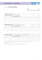
FischerKLIPTEC – Load Tables Load Values Wind Suction/Uplifting Load tables as per DIN 18807, Section 2. Single-span support Dead weight g [kN/m²] Permissible load q [kN/m²] in span L [m] Double-span support End support width a ≥ 40 mm Intermediate support width b 60 mm ≥ Dead weight g [kN/m²] Permissible load q [kN/m²] in span L [m] Triple-span support End support width a ≥ 40 mm Intermediate support width b 60 mm ≥ Dead weight g [kN/m²] Permissible load q [kN/m²] in span L [m] In addition, proof of the fastening connections must be provided. Smaller permissible spans could result from this....
Open the catalog to page 13All Fischer Profil GmbH catalogs and technical brochures
 FischerTHERMsolar
12 Pages
 FischerPANEEL - Façade panels
12 Pages
 FischerSONIC
8 Pages
 FischerFIREPROOF
4 Pages
 flashings catalogue
80 Pages
 FischerTHERM - Sandwich elements
36 Pages


- Profiled sheet
- Steel sheet metal
- Facade profiled sheet
- Metal roofing
- Metal facing sandwich panel
- Aluminum profiled sheet
- Roof acoustic sandwich panel
- Facade acoustic sandwich panel
- Decorative profiled sheet
- Ribbed sheet metal
- Mounting system
- Photovoltaic panel mounting system
- Solar mounting system
- Corrugated roofing
- Corrugated sheet metal
- Sheet steel roofing
- Airtight adhesive strip
- Galvanized steel sheet metal
- Foam core sandwich panel