
Catalog excerpts
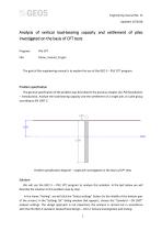
Engineering manual No. 15 Updated: 07/2018 Analysis of vertical load-bearing capacity and settlement of piles investigated on the basis of CPT tests Program: The goal of this engineering manual is to explain the use of the GEO 5 – PILE CPT program. Problem specification The general specification of the problem was described in the previous chapter (12. Pile foundations – Introduction). Analyse the load-bearing capacity and the settlement of a single pile, or a pile group according to EN 1997-2. Problem specification diagram – single pile investigated on the basis of CPT tests Solution We will use the GEO 5 – PILE CPT program to analyse this problem. In the text below we will describe the solution to this problem step by step. In the frame “Setting”, we will click the “Select settings” button (in the middle of the bottom part of the screen). In the “Settings list” dialog window that appears, choose the “Standard – EN 1997” analysis settings. The design approach is not important, the analysis is carried out in accordance with the EN 1997-2 standard: Geotechnical Design – Part 2: Ground inv
Open the catalog to page 1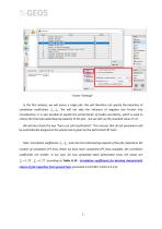
Frame “Settings“ In the first analysis, we will assess a single pile. We will therefore not specify the reduction of correlation coefficients 3 , 4 . We will not take the influence of negative skin friction into consideration. It is also possible to specify the partial factor of model uncertainty, which is used to reduce the total calculated bearing capacity of the pile – but we will use the standard value of 1.0. We will also check the box “Carry out soil classification”. This ensures that all soil parameters will be automatically assigned in the whole task as given by the performed...
Open the catalog to page 2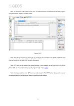
Now, we will move to the “CPT” frame. Here, we will import the completed tests into the program using the button “Import” and then “Add”. Frame “CPT“ Note: The files for import (cpt_test1.gef, cpt_test2.gef) are included in the GEO5 installation and they are located in the folder FINE in public documents. Note: CPT tests can be imported in several formats, in our example, we will use tests in the Dutch format GEF. For more information, see the program help – F1 or online. Note: It is also possible to enter CPT tests manually using the “Add CPT” button. Because the amount of measured points...
Open the catalog to page 3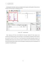
By clicking the "OK" button, the tests are loaded into the program and the graphs of measured cone resistance and local friction are displayed onscreen. Cone resistance Local friction Pore pressure [$0 Soil classification § Profile 0 Soils G Assign Ittl Construction ft Geometry Visualized field test [ferj List of pictures Frame "CPT" - imported tests Note: Simply put, CPT tests can be divided into two types. Standard CPT tests measure cone resistance (qc) and skin friction (fs). The second type is a more detailed test called CPTu, which measures pore pressure as well. The CPTu test is more...
Open the catalog to page 4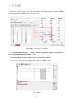
Select "cpt_test1" and click on the "Edit No. 1" button. After pressing the "Edit" button, a dialog window appears with detailed results of the selected test. Edit field test properties (cone penetration test) Local friction Depth of the 1st point from original terrain Cone resistance qc[MPa] Ground water Depth of GWT from the 1st point of test Frame "CPT" - pore pressure calculation In this dialog window, press the "Calculate u2" button in the bottom left part of the screen and enter the supposed ground water table at 4,50 m. We will perform the calculation of pore pressure for both tests...
Open the catalog to page 5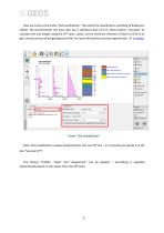
Now we move to the frame "Soil classification". We select the classification according to Robertson (2010). The penetrometer net area ratio has a standard value of 0,75. Select option "calculate" to calculate the unit weight using the CPT tests. Lastly, set the minimum thickness of layer to 0,50 m to get a clearer picture of the geological profile. For more information see the program help - F1 or online. Soil classification Sand mixtures - silty sand to sandy silt ft Bearing capacity IHSil Settlement Name of test: : cpt_testl Depth of the 1st point from original terrain : di 0,00 m...
Open the catalog to page 6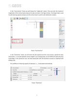
In the “Construction” frame we will choose the “single pile” option. Then we enter the maximum magnitude of the vertical load acting on the pile as shown in the figure below. The design load is used for pile bearing capacity analysis and the service load is used for pile settlement analysis. Frame “Construction“ In the “Geometry” frame, we will enter the pile material and the cross-section, specify the basic dimensions, i.e. the pile diameter and its length in soil. Subsequently, we will define the pile execution technology. In this particular case, we have bored piles with the borehole...
Open the catalog to page 7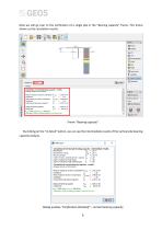
Now we will go over to the verification of a single pile in the “Bearing capacity” frame. This frame shows us the calculation results. Frame “Bearing capacity” By clicking on the “In detail” button, we can see the intermediate results of the vertical pile bearing capacity analysis. Dialog window “Verification (detailed)“ – Vertical bea
Open the catalog to page 8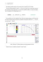
Note: Bearing capacity analysis can be carried out for one specific test or for all tests. The vertical bearing capacity of a pile Rc ,d is the sum of the skin friction and pile base resistance (for more details visit the program help – F1). To meet the reliability condition, its value must be higher than the magnitude of the acting design load Fs , d . Then we will go over to the “Settlement” frame, where the ultimate loading curve for the pile and the results of the pile settlement calculation are displayed. The total pile settlement is w1, d = 15,6 mm for service load Fs = 300 kN . Frame...
Open the catalog to page 9All FINE catalogs and technical brochures
-
Pile
18 Pages
-
FIN EC Edition 2017
826 Pages
-
Settlement
11 Pages
-
Gravity wall
10 Pages
-
geotechnical GEO5 groundloss
2 Pages
-
GEO5 leaflet
2 Pages


