
Catalog excerpts
User's Guide FIN EC Edition 2017
Open the catalog to page 1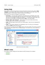
Using help Help window can either be launched by directing through the program menu (items "Help", "Content") or by pressing "F1" button anywhere in the program. If using "F1" button, the dedicated page for active program mode or window will be displayed. These tools can be used for navigation in Help window: • Tree menu - List of the topics organized in the tree structure. Left-button click on the topic launches corresponding page in the right part of the window. The branches of the tree menu can be hidden by clicking the symbols "+/-" in front of the topic's name. The tree menu can be...
Open the catalog to page 16
Version 4 The version 4 was released on 31 October 2014. It brings these features: New program Concrete Fire • Fire resistance of RC members according to EN 1992-1-2 • Determination of temperature in concrete and reinforcement bars • General combination of actions (normal and shear forces, bending and torsional moments) • Nominal and parametric fire exposure curves • Basic and accidental loads, import of loads from file • Analysis according to 500°C isotherm method or Zone method • Import of projects created in programs "Concrete 2D" and "Concrete 3D" Fin 2D, Fin 3D • Members with excluded...
Open the catalog to page 17
FIN EC - User's Guide © Fine Ltd. 2016 • Timber Fire - analysis of built-up cross-sections • Section - import of DXF file Version 5 Version 5 of the program "Fin EC" was released on 24th March 2015. It contains these new features: Enhanced user interface in programs Fin 2D and Fin 3D (spring 2016) Main improvements of user interface are: • Graphical input of joints and members in "Fin 3D" • Context menus for tables and workspace • Easier selections in the workspace and tables • Changes in the tree menu • Easier editing of joints and members All improvements are described in a dedicated...
Open the catalog to page 18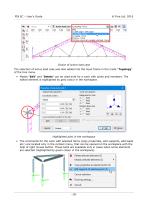
Choice of active load case The selection of active load case was also added into the input frame in the mode "Topology" of the tree menu. • Modes "Edit" and "Delete" can be used both for a work with joints and members. The edited element is highlighted by grey colour in the workspace. Highlighted joint in the workspace • The commands for the work with selected items (copy properties, edit supports, add loads etc.) are located only in the context menu, that can be opened on the workspace with the help of right mouse button. These tools are available only in cases when some elements are...
Open the catalog to page 19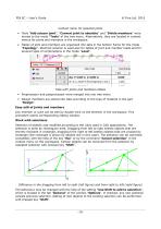
FIN EC - User's Guide © Fine Ltd. 2016 Context menu for selected joints • Tools "Add scissor joint", "Convert joint to absolute" and "Divide members" were moved to the mode "Tools" of the tree menu. Alternatively, they are located in context menus for joints and members in the workspace. • Tables of joint and members are organized into tabs in the bottom frame for the mode "Topology". Identical solution is used also for tables of joint and member loads and for several types of combinations in the mode "Load". Tabs with joints and members tables • Preprocessor and postprocessor were merged...
Open the catalog to page 20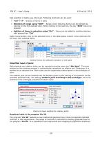
Also selection in tables was improved. Following shortcuts can be used: • "Ctrl"+"A" - Selects all items in table • Selection of range using "Shift" - Range (more following items) can be selected by clicking on the first and last item. When clicking on the last one, the key "Shift" has to be pressed. • Addition of items to selection using "Ctrl" - Items can be added to existing selection with pressed key "Ctrl". Right mouse button click on the selected items in the table opens context menu with tools for the work with selected items. Context menu for selected members in the table Simplified...
Open the catalog to page 21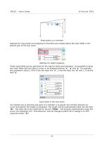
Snap points on a member Settings for snap points and snapping to directions are located above the input fields in the bottom part of the tree menu. Settings for object snapping These input fields can be used both for the input of joints and members. It is possible to jump into input fields with the help of cursor or by keyboard entries "x", "y" and "z". For example, the expression x0y2z1.3 fills 0 into the input line "x", 2 into the input line "y" and 1.3 into the field "z". Input fields in the tree menu The easiest way of entering end point of a member is to specify the member direction by...
Open the catalog to page 22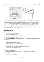
FIN EC - User's Guide © Fine Ltd. 2016 Definition of member direction by the cursor and input of member length with the help of keyboard Alternatively, it is possible to use extended options of input fields in tree menu. Input fields "X" "Y" and "Z" are usable for the definition of the end point with the help of global coordinates, fields "r" and "a" define the end point by the member length and rotation about the axis y. Buttons "A" changes whether the input is considered in the global coordinate system or relatively to the beginning of the member. It is possible to jump into input fields...
Open the catalog to page 23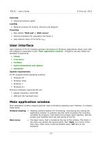
FIN EC - User's Guide © Fine Ltd. 2016 Concrete • Improved analysis speed Loading • National annexes for Austria, Slovenia and Bulgaria Punching • New details "Wall end" a "Wall corner" • General procedure for calculation the factor • User-defined value of the factor kmax User interface User interface of Fin EC respects general conventions of Windows applications. Basic work with the software is described in part "Main application window". Programs use also these nonstandard components: • Tables • Tree menu • Toolbars • Active dimensions and objects • Calculator System requirements Fin EC...
Open the catalog to page 24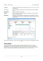
FIN EC - User's Guide © Fine Ltd. 2016 FIN EC - User's Guide © Fine Ltd. 2016 Toolbars Tree menu Workspace Frame Status bar • Toolbars with frequently used commands (documentation printing, view adjustments). • The main graphical control element, that divides the work into logical parts. • Graphical display of the project. • Frame is located in the bottom part of the window, it contains control elements for data inputs. • Status bar is placed along the bottom edge of the application window. Some additional information is displayed there (design standard, cursor position etc.). Main window:...
Open the catalog to page 25All FINE catalogs and technical brochures
-
Pile
18 Pages
-
Pile CPT
12 Pages
-
Settlement
11 Pages
-
Gravity wall
10 Pages
-
geotechnical GEO5 groundloss
2 Pages
-
GEO5 leaflet
2 Pages


