Catalog excerpts
AVVERTENZE SULLA SICUREZZA SAFETY WARNINGS • The respect of these instructions does not exempt from compliance with all safety regulations in force in the country where you use the system. • These instructions are intended for users of TF products and systems. Each one must be aware of the contents of this manual; in case they have difficulties in reading the same, the employer has to provide education of the same • The User’s Manual instructions must always be available at the workplace for all operators • This manual, even if used in order to draw up a Method Statement, will not...
Open the catalog to page 2
TUBE & COUPLERS BRACING 20 TRANSPORT & STORAGE 20 DEGLI ELEMENTI ISTRUZIONI DI MONTAGGIO 14
Open the catalog to page 3
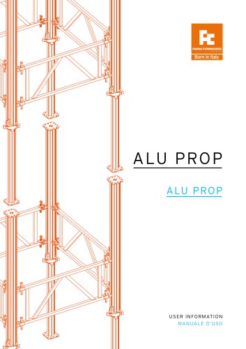
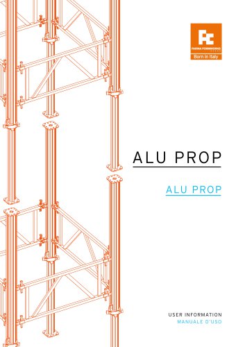
TF Alu Towers is the ideal solution in order to realize in situ heavy slabs at relevant heights, offering the necessary loadability and a working area at height by Aluminium Heavy Duty Props and system components as Connecting Frames wich stabilize the towers and increasing the loadability. TF Alu Towers è la soluzione ideale per la realizzazione di solai in opera con carichi elevati ed altezze rilevanti, garantendo la necessaria portata ed il raggiungimento della quota di lavoro attraverso I Puntelli in Alluminio ad alta portata ed I componenti di sistema quali I Telai di collegamento che...
Open the catalog to page 5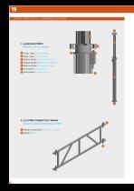
SYSTEM COMPONENTS | COMPONENT! SISTEMA 1. ALUMINIUM PROPS PUNTELLI IN ALLUMINIO ^ Outer Tube | Tubo esterno © Inner Tube | Tubo interno © Safety Hook | Sancio di sicurezza ©Adjusting Nut | 3hiera di regolazione © Bearing Plate | 'langia portante © Foot plate | 'langia di base G Head Plate | Flangia di testa 2. ALU PROP CONNECTING FRAMES TELAI DI COLLEGAMENTO ALU PROP ©Wedge Connection | Morsetto a cuneo Blwedge | Cuneo
Open the catalog to page 6
PROLUNGHE PUNTELLI ALU PROP A Outer Tube | Tubo esterno B End plates | Flange di testa 6. ALU PROP WALING CONNECTOR CONNETTORE CORRENTI ALU PROP Flangia di base B Adjusting nut Ghiera di regolazione C Connecting plateù Flangia di collegamento Gancio di fissaggio B Connecting plate Piastra di collegamento C Threaded rod M 16 Barra filettata M 16 D Nut M 16 Dado M 16 8. ALU PROP CLAMP & COUPLER 7. ALU PROP CONNECTING BOLT MORSETTO & GIUNTO ALU PROP BULLONE DI FISSAGGIO ALU PROP
Open the catalog to page 7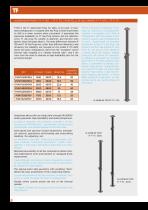
ALUMINIUM PROPS TF P 105 / TF P 70 | PUNTELLI IN ALLUMINIO TF P 105 / TF P 70 P 105 is the TF Aluminium Prop for slabs, to be used in standard configuration or coupled with Alu Prop Connecting Frames to shift to a tower systems when convenient. It guarantee the maximum loadability os TF Alu Prop System, but are substituted by TF Alu prop 70, smaller in diameter and therefor even lighter, when the loads allow it. The main differences between P 105 and P 70 Alu Props are, other than different diameters, and obviuosly the lodabilty, are focused on the model P 70 L420, where the prop...
Open the catalog to page 8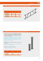
ALU PROP CONNECRTING FRAMES | TELAI DI COLLEGAMENTO ALU PROP
Open the catalog to page 9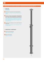
CONNECTING TF ALU PROPS EXTENSIONS | CONNESSIONE PROLUNGHE ALU PROP TF A Position the TF ALu Prop on the choosed extension Posizionare il Puntello TF Alu Prop sull’estensione predefinita B Insert four Alu Prop Connecting Bolt in dedicated Prop and Extension plate holes (diagonally corresponding so that a “square” will be formed) and securely screw them Inserire Quattro Bulloni di fissaggio Alu Prop negli appositi fori delle flange di puntello e prolunga (corrispondenti in diagonale così da formare un “quadrato”) e serrali adeguatamente C Alu Prop and it’s extension are now correctly fixed...
Open the catalog to page 10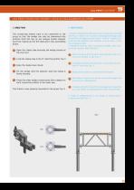
ALU PROP CONNECTING FRAMES | TELAI DI COLLEGAMENTO ALU PROP The connecting frames have to be connected to the props so that the wedge can only be hammered into position from the top, as per images beside showed. Alu Prop Tripods are be the ideal aid in this assembling phase. I Telai di collegamento devono essere collegati ai puntelli Alu Prop in modo che il cuneo di serraggio dell’apposito morsetto di fissaggio possa essere “chiuso” tramite colpi di martello agendo solo dall’alto verso il basso, come da immagini a lato. I treppiedi Alu Prop sono l’accessorio ideale come supporto per questa...
Open the catalog to page 11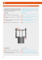
ALU PROP WALING CONNECTOR | CONNETTORE CORRENTI ALU PROP In presence of high loads, steel walers can be adopted as main beams, and can be fixed to the props instead of H20 wooden beams, i.e. when configuring TF Alu Prop shoring towers as “Table System”. In presenza di carichi elevate, correnti in acciaio possono essere adottati e fissati ai puntelli al posto delle comuni travi in legno H20. p.e. : configurando il Sistema TF Alu Prop come “Tavolo Solaio”. A Svitare il dado M 16 dalla barra filettata M 16 (1) B Position the connecting plate on U-profile top B Posizionare la piastra di...
Open the catalog to page 12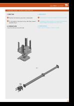
FOUR WAY HEAD | TESTA A QUATTRO VIE 1. MONTAGGIO A Position the head on prop foot or head plate A Posizionare la testa sulla flangia di testa del puntello B Fix the head to the prop by four Alu Prop connect- B Collegare la Testa a quattro vie al puntello mediante quattro Bulloni di fissaggio Alu Prop Fig. 6 Loosen the bolts and remove the head. Svitare i Bulloni di fissaggio e rimuovere la testa.
Open the catalog to page 13
ASSEMBLING INSTRUCTIONS | ISTRUZIONI DI MONTAGGIO TF ALU PROP PREPARATION PREPARAZIONE PUNTELLI TF ALU PROP: A Press the safety hook (1) and release the adjusting A Aprire il gancio di sicurezza (1) e svitare la ghiera di regolazione (2). B Extract the inner tube (3) to required prop length. B Estrarre il tubo interno sino alla necessaria lunghezza (3). C The inner tube have to be pushed in until the adjust- C Il tubo interno deve essere spinto verso l’interno sino all’appoggio della ghiera di regolazione sulla flangia portante (4). ing nut lies on the bearing plate (4). D Lock the safety...
Open the catalog to page 14
TF ALU PROP CONNECTION | GIUNZIONE PUNTELLI TF ALU PROP: TF ALU PROP CONNECTING BOLT – BULLONE DI FISSAGGIO ALU PROP BULLONE DI FISSAGGIO ALU PROP The Connecting Bolt allow to “couple” two Alu Props trough their end plate ( four bolts for each connection) Fig. 8 Il Bullone di Fissaggio permette la giunzione di due puntelli Alu Prop fissandone le flange (quattro bulloni per ogni giunzione) Fig. 8 A Position the two props on top of each other mak- A Posizionare I due puntelli uno sull’altro assicurandosi che le flange si sovrappongano precisamente (1) ing sure the flanges match precisely (1)...
Open the catalog to page 15All Farina Formworks catalogs and technical brochures
-
Adjustable PROPS
11 Pages
-
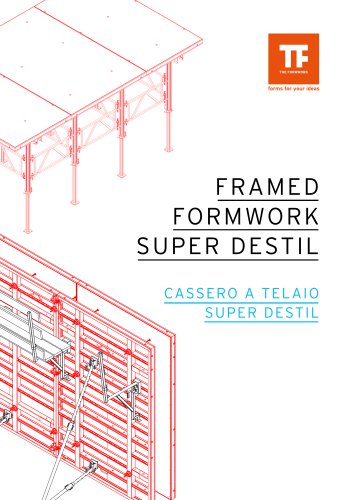
FRAMED FORMWORK SUPER DESTIL
37 Pages
-
SLAB MODULAR SYSTEM UNIDECK
8 Pages
-
DESTIL SINGLE SIDE SHUTTERING
32 Pages
-
DESTIL CLIMBING SYSTEM
24 Pages
-
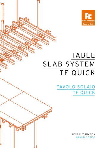
TABLE SLAB SYSTEM QUICK
24 Pages
-
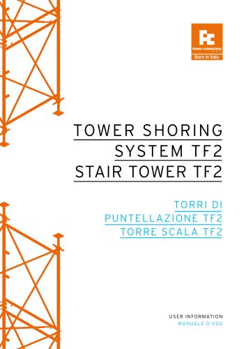
TF2 SHORING TOWERS
36 Pages
-
SLAB MODULAR SYSTEM DECK
32 Pages
-
DESTIL2 LIGHT WALL FORMWORK 60KN
52 Pages
-
DESTIL WALL FORMWORK 80KN
52 Pages
-
DESTIL MINI
48 Pages
-
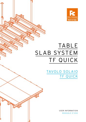
TABLE SLAB SYSTEM TF QUICK
24 Pages
-
ALU PROP
24 Pages
-
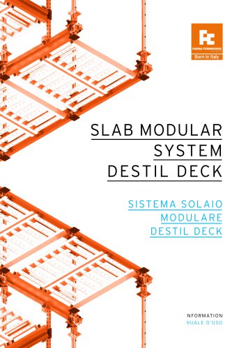
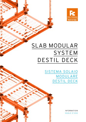
SLAB MODULAR SYSTEM DESTIL DECK
32 Pages
-
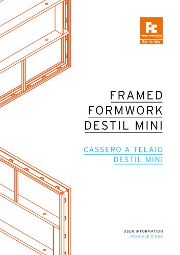
DESTIL FRAMED FORMWORK
48 Pages

