DF700
1 /2Pages
DF700
1 /2Pages
Catalog excerpts

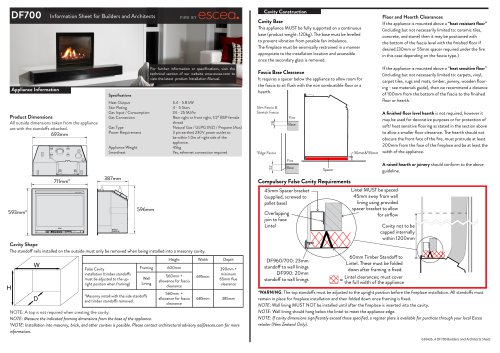
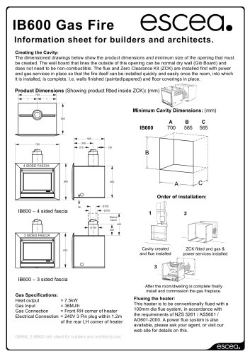
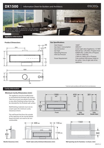
Cavity Construction Information Sheet for Builders and Architects Floor and Hearth Clearances Cavity Base This appliance MUST be fully supported on a continuous base (product weight: 120kg). The base must be levelled to prevent vibration from possible fan imbalance. The fireplace must be seismically restrained in a manner appropriate to the installation location and accessible once the secondary glass is removed. Slim Fascia & Appliance Information Product Dimensions All outside dimensions taken from the appliance are with the standoffs attached. Heat Output 5.4 - 5.8 kW Star Rating 4 - 5 Stars Gas Input / Consumption 24 - 25 MJ/hr Gas Connection Rear right or front right, 1/2” BSP female thread Gas Type Natural Gas / ULPG (NZ) / Propane (Aus) Power Requirement 3 pin earthed 230V power outlet to be within 1.0m of right side of the appliance. Appliance Weight 45kg Smartheat Yes, ethernet connection required Fire Fascia Base Clearance Base It requires a spacer below the appliance to allow room for the fascia to sit flush with the non combustible floor or a hearth. Slim Fascia & Stretch Fascia 28 For further information or specifications, visit the technical section of our website www.escea.com to view the latest product Installation Manual. Fire Lorem 45mm Spacer bracket (supplied, screwed to *Edge Fascia pallet base) Fire Overlapping Base join to face Lintel Cavity Shape The standoff rails installed on the outside must only be removed when being installed into a masonry cavity. Height False Cavity installation (timber standoffs must be adjusted to the upright position when framing) A raised hearth or joinery should conform to the above guideline. Compulsory False Cavity Requirements If the appliance is mounted above a “heat sensitive floor” (including but not necessarily limited to: carpets, vinyl, carpet tiles, rugs and mats, timber, joinery, wooden flooring - see materials guide), then we recommend a distance of 100mm from the bottom of the fascia to the finished floor or hearth. A finished floor level hearth is not required, however it may be used for decorative purposes or for protection of soft/ heat sensitive flooring as stated in the section above to allow a smaller floor clearance. The hearth should not obscure the front face of the fire, must protrude at least 200mm from the face of the fireplace and be at least the 30mm&*55mm width of the appliance. If the appliance is mounted above a “heat resistant floor” (including but not necessarily limited to: ceramic tiles, concrete, and stone) then it may be positioned with the bottom of the fascia level with the finished floor if desired.(30mm or 55mm spacer required under the fire in this case depending on the fascia type.) Framing Wall Lining 390mm + minimum 65mm flue clearance 600mm 560mm + allowance for fascia clearance *Masonry install with the side standoffs and timber standoffs removed. 560mm + allowance for fascia clearance NOTE: A top is not required when creating the cavity. NOTE: Measure the indicated framing dimensions from the base of the appliance. *NOTE: Installation into masonry, brick, and other cavities is possible. Please contact architectural advisory [email protected] for more information. DF960/700: 23mm standoff to wall linings DF990: 20mm standoff to wall linings Lintel MUST be spaced 45mm away from wall lining using provided spacer bracket to allow for airflow Cavity not to be capped internally within 1200mm 60mm Timber Standoff to Lintel. These must be folded down after framing is fixed. Lintel clearances; must cover = the full width of the appliance *WARNING: The top standoffs must be adjusted to the upright position before the fireplace installation. All standoffs must remain in place for fireplace installation and then folded down once framing is fixed. NOTE: Wall lining MUST NOT be installed until after the fireplace is inserted into the cavity. NOTE: Wall lining should hang below the lintel to meet the appliance edge. NOTE: If cavity dimensions significantly exceed those specified, a register plate is available for purchase through your local Escea retailer (New Zealand Only). 630426_4 DF700 Builders and Archi
Open the catalog to page 1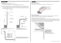
Flue Information Flue Configuration (If more than 4m flue length is required) If your flue system is less than 4m long: • A simple aluminium flexible flue is required without insulation (see diagrams below). If your flue system is greater than 4m long (as shown in diagrams below), then there are the following options: • For flue run installations beyond 4m and up to 12m, flexi flue must be used for the entire flue run and must be fully insulated from appliance connection to fan unit. Beyond 12m (up to 40m) please contact the Escea Advisory Team at [email protected]. UVP Cowl The fire chassis is zero...
Open the catalog to page 2All Escea catalogs and technical brochures


Archived catalogs
 Australia Product Brochure
12 Pages
 New Zealand Product Brochure
24 Pages
 New Zealand River Rock
1 Page
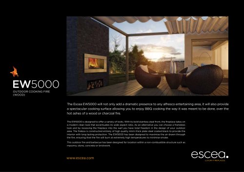 EW5000 Open Garden Fireplace
2 Pages
 United Kingdom Product Brochure
24 Pages
 United States Product Brochure
12 Pages
- Contemporary fireplace
- Closed hearth fireplace
- Home fireplace
- Built-in fireplace
- Single-sided fireplace
- Glass fireplace
- Wood-burning fireplace
- Rectangular fireplace
- Open fireplace
- Steel fireplace
- Gas fireplace
- Wall fireplace
- Double-sided fireplace
- Outdoor fireplace
- Wall-mounted fireplace
- Corner fireplace
- Free-standing fireplace
- Stone fireplace
- Stainless steel fireplace