MULTIFlow MFC

MULTIFlow MFC
Elta Fans Limited presents the Multiflow MFC series, a range of mixed flow circular ducted fans featuring a patented mixed flow impeller with adjustable blade geometry. This innovation offers advantages over traditional fans, such as non-stall airflow and a non-overloading power curve.
Standard MFC Range
The series includes nine fan sizes, each with two speed options and five factory-set impeller blade angles, resulting in 90 standard model options. The fans are fully cased with circular mounting flanges and include a wired terminal box for easy installation.
Performance Data
Performance testing complies with ISO 5801:1997 and BS 848 standards. Fans are tested for aerodynamic and sound performance, with static pressure as a key metric. Performance curves show capabilities at specified speeds, with speed adjustments possible.
Electrical and Dimensional Data
Electrical data and motor selection details are provided for each model, considering speed adjustments. Dimensional data ensures compatibility with standard duct sizes.
Accessories and Mounting
Accessories such as silencers and mounting arrangements are available to enhance performance. Detailed specifications guide selection and installation.
How to Specify
Guidelines are provided for selecting the appropriate fan model based on performance needs, including airflow, pressure, and sound levels.
Conclusion
The Multiflow MFC series offers a compact, efficient solution for diverse air movement needs, with performance and space-saving benefits over conventional designs.
General Specification – Multiflow Range of MFC Fans
The MFC range features adjustable pitch Mixed Flow Fan units for circular ductwork, with accessories like silencers. Casings are made from galvanized steel, and guide vanes and motor support arms are aerodynamically designed.
Impeller and Motor Details
The impeller's blade angle is factory-set, made from aluminum and steel, and finished with yellow epoxy powder. Motors are centrally located, designed to IP55 standards, and pre-wired for easy connection.
Quality and Compliance
Design and manufacturing are ISO 9001 certified. Fan units are CE marked, complying with relevant EU directives.
Product Variants
- Standard Axial: Long and short cased, belt-driven models.
- Bifurcated: For hostile air movement up to 250ºC.
- Smokevent: For emergency ventilation at temperatures up to 400ºC.
- Multiflow MFB: Square cased units for general ventilation.
- Compact 2000: Compact axial fans for various applications.
- Customised Solutions: Tailored solutions for specific needs.
Contact Information
Elta Fans Ltd has offices in Hampshire and West Midlands, UK. More information is available at eltafans.com or via email at [email protected].
Catalog excerpts
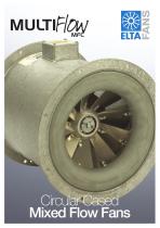
Circular Case Mixed Flow Fans
Open the catalog to page 1
MFC series Mixed Flow ‘Circular’ Ducted Fans Advanced, flexible performance fan technology Contents Multiflow Technology Performance Data Electrical Data Dimensional Data • Less space • In-line or end of duct fitting Mounting Arrangements Other Elta Products Multiflow MFC benefits • More performance Multiflow is a trade name of Elta Fans
Open the catalog to page 3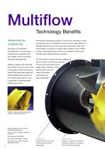
Multiflow Technology Benefits Advanced fan engineering Elta Multiflow technology provides for the first time, the ability to select a single direct driven mixed flow fan that can meet a wide selection of alternative performance contours and duty requirements. With fixed The secret of Elta Multiflow blade designs, the choice is to either make a selection from a limited technology lies in its extensively number of fixed performance contours or, consider the more costly researched and patented mixed and less space efficient belt driven variants. flow impeller, which incorporates adjustable blade...
Open the catalog to page 4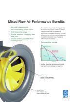
Mixed Flow Air Performance Benefits • Non-stall characteristic The inherent aerodynamic benefits of good mixed • Non-overloading power curve flow impeller design provide marked advantages • Wide operating range over conventional axial and centrifugal air performance characteristics. Mixed flow ‘non-stall’ • Greater pressure capability than axial fans airflow properties and a non-overloading absorbed power curve allow a wide range of operating • Greater airflow capability than centrifugal fans Comparative curves MULTIFLOW ‘MIXED FLOW’ Multiflow, mixed flow performance can provide clear benefits...
Open the catalog to page 5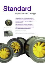
Standard Multiflow MFC Range The Multiflow MFC fan range has been designed to provide customers with all the inherent benefits of Elta mixed flow technology by optimising design and performance choice. 9 fan sizes each with 2 alternative speeds and a selection of 5 alternative, factory set impeller blade angles for each model, provide an impressive choice Motor and stator Guide Vanes of 90 standard model/performance options. MFC Standard supply comprises Fully cased, cylindrical model with circular mounting flanges at both ends. Wired terminal box, ready for customer installation.
Open the catalog to page 6
Basic Fan Model Reference Improved Performance The unique design of Multiflow MFC fans enables required performance to be achieved from a smaller airstream leaving a Multiflow MFC impeller being more axially orientated. This permits the casing to be closer fan size than is normally achievable with typical conical style, fixed blade mixed flow fans. This is due to the to the impeller periphery, without incurring losses and thereby retaining excellent air performance, power and sound levels. Also, as Multiflow MFC incorporates an impeller of relatively wide air passage design, the resultant air...
Open the catalog to page 7
Airflow Performance Data Elta fan performance data is achieved through exhaustive testing in the Company’s laboratory and provides an accurate and reliable record of the MFC series performance. Testing has been performed for Type D installation category (fully ducted) to the following current standards. Aerodynamic Performance To ISO 5801 : 1997 (incorporating BS 848 Part 1:1997) Sound Performance To BS 848 Part 2 : 1985 on both Inlet and Outlet sides Pressure Values The ISO 5801 standard suggests that fan pressure should be shown as total or stagnation values, with static pressure illustrated...
Open the catalog to page 8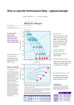
How to read Air Performance Data – typical example Model Reference Impeller Speed MFC315 1440 rpm Fan Series Casing Dia (mm) Density 1.2kg/m3 Sound Level spectra when Values shown are the overall In-duct Sound Power levels refer to Sound Level notes and table below. below this contour 71 Overall inlet side variations are shown in sound level 60 data below. Pd, Fan Dynamic Pressure Curve Volume/Pressure Characteristic Impeller Blade Setting selected blade angle opposite page. Factory pre-set blade angle setting reference. Customers specify 1 to Selection Example An airflow of 0.24 m3/sec against...
Open the catalog to page 9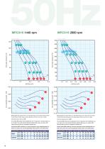
0.10 Sound Level The values shown on the performance curve above are the overall In-duct Sound Power levels on the outlet side of the fan unit. (rel. to 1pW). Sound Level The values shown on the performance curve above are the overall In-duct Sound Power levels on the outlet side of the fan unit. (rel. to 1pW). Inlet side values vary by +1dB. Inlet side values vary by +0dB. The overall dBW values may be adjusted by the ‘A’ reductions in the table below, so as to result in the mean free field spherical radiated dBA value at 3 metres. dBA values should be used for comparative purposes only. The...
Open the catalog to page 10
0.4 0.2 Sound Level The values shown on the performance curve above are the overall In-duct Sound Power levels on the outlet side of the fan unit. (rel. to 1pW). Sound Level The values shown on the performance curve above are the overall In-duct Sound Power levels on the outlet side of the fan unit. (rel. to 1pW). Inlet side values vary by +1dB. Inlet side values vary by -1dB. The overall dBW values may be adjusted by the ‘A’ reductions in the table below, so as to result in the mean free field spherical radiated dBA value at 3 metres. dBA values should be used for comparative purposes only....
Open the catalog to page 11
0.05 Sound Level The values shown on the performance curve above are the overall In-duct Sound Power levels on the outlet side of the fan unit. (rel. to 1pW). Sound Level The values shown on the performance curve above are the overall In-duct Sound Power levels on the outlet side of the fan unit. (rel. to 1pW). Inlet side values vary by +1dB. Inlet side values vary by +1dB. The overall dBW values may be adjusted by the ‘A’ reductions in the table below, so as to result in the mean free field spherical radiated dBA value at 3 metres. dBA values should be used for comparative purposes only. The...
Open the catalog to page 12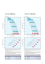
0.05 0.1 Sound Level The values shown on the performance curve above are the overall In-duct Sound Power levels on the outlet side of the fan unit. (rel. to 1pW). Sound Level The values shown on the performance curve above are the overall In-duct Sound Power levels on the outlet side of the fan unit. (rel. to 1pW). Inlet side values vary by +1dB. Inlet side values vary by +1dB. The overall dBW values may be adjusted by the ‘A’ reductions in the table below, so as to result in the mean free field spherical radiated dBA value at 3 metres. dBA values should be used for comparative purposes only....
Open the catalog to page 13All Elta catalogs and technical brochures
 EKA
EKA16 Pages
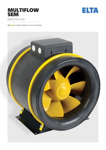 MULTIFLOW SEM
14 Pages
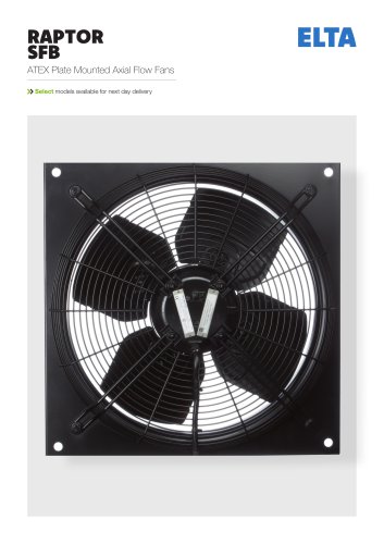 RAPTOR SFB
8 Pages
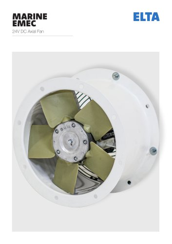 MARINE EMEC
10 Pages
 MULTIFloW MFB
28 Pages
 JetVent
12 Pages
 COMPACT POWERPLUS
12 Pages
 HERITAGE FCE/FCD
8 Pages
 Biflow Cylindrical/ Conical
4 Pages
 Smoke Vent
8 Pages
 Compact SCDA
7 Pages
 Compact SCPA
6 Pages
 Compact Range
15 Pages
 Window Wall Fan SAX
5 Pages
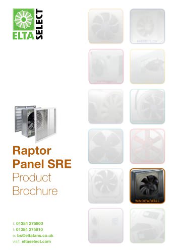 Raptor Panel SRE
6 Pages
 Ezifit Thru-wall SEWE
5 Pages
 Ezifit in-wall SEIE
5 Pages
 Multiflow SMT
6 Pages
 Multiflow SMC
8 Pages
 Multiflow SMB
8 Pages
 Heat Recovery Units
5 Pages
 SWHR180 Heat Recovery Unit
4 Pages
 ZOO Fan SDF
6 Pages
 Ceiling Fan HCF
4 Pages
 Wall Fan HWFA
5 Pages
 Raptor Cooler SRC
5 Pages
 Pedestal Fan HPFA
5 Pages
 Viper SCC
11 Pages
 Twinflow STD
15 Pages
 Slim Qube SSQU-HT
6 Pages
 Singleflow SSD
15 Pages
 Quietflow SQS
15 Pages
 Quietflow SQT
15 Pages
 Quietflow SQT DCV
16 Pages
 Quietflow SQS DCV
16 Pages
 Quietflow Classic SQT
5 Pages
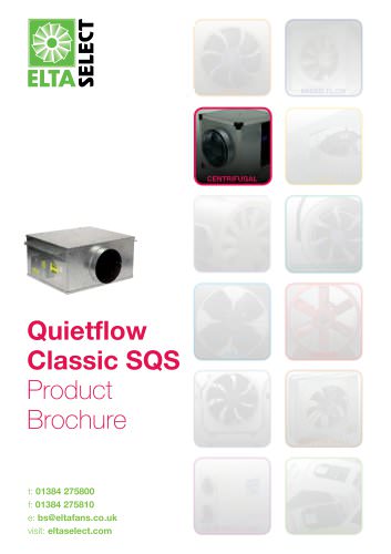 Quietflow Classic SQS
5 Pages
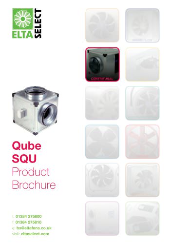 Qube SQU
6 Pages
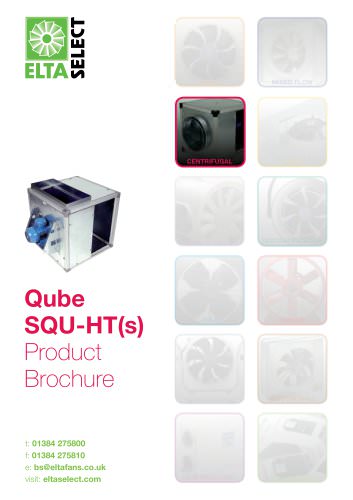 Qube SQU-HT
6 Pages
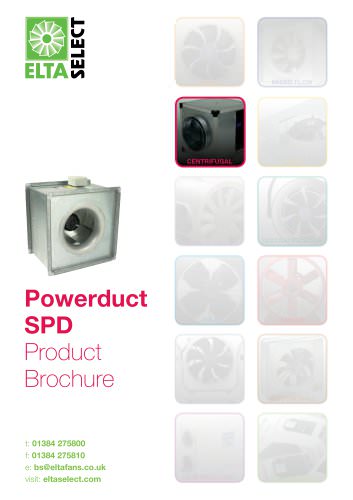 Powerduct SPD
7 Pages
 Jetstream SJS
6 Pages
 Jetflow HIT
9 Pages
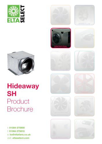 Hideaway SH
11 Pages
 Biflow SB (CYL)
5 Pages
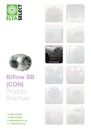 Biflow SB (CON)
7 Pages
 Revolution SLC
14 Pages
 Raptor SPA
16 Pages
 Raptor SDA
18 Pages
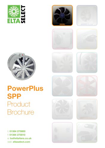 PowerPlus SPP
6 Pages
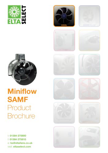 Miniflow SAMF
6 Pages
 Compact SCP
8 Pages
 Compact PowerPlus SCPP
5 Pages
 SLCX Atex
7 Pages
 Raptor SFB Atex
5 Pages
 Twinflow STDR
14 Pages
 Twinflow STDR DCV
11 Pages
 Skyflow Viper SSC
12 Pages
 Skyflow SSRV
16 Pages
 Skyflow SSR
17 Pages
 Singleflow SSDR
13 Pages
 Singleflow SSDR DCV
10 Pages
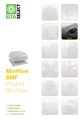 Miniflow SMF
5 Pages
 Heritage SCHT
7 Pages
 Heritage SGE
5 Pages
 Heritage SCH
6 Pages
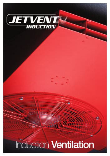
 JETVENT INDUCTION
16 Pages
 Jetvent Axials
12 Pages
 BELT DRIVE BD
13 Pages
 LC/SC
LC/SC28 Pages
 Centrifugal JetVent Mixed
12 Pages
 JetVent Flanged
12 Pages
 ATEX Fans
4 Pages


- Metal fan
- Industrial thermostat
- Surface-mounted detector
- Commercial fan
- Indoor fan
- Mechanical ventilation unit
- White detector
- Commercial detector
- Programmable thermostat
- Ventilation controller
- Digital thermostat
- Extractor fan
- Wall-mounted ventilation controller
- Duct fan
- Industrial fan
- Domestic fan
- Wall-mount fan
- Commercial ventilation controller