EKA
1 /16Pages

EKA
1 /16Pages
Catalog excerpts
MATIKA www.ventmatika.com ELECTRICAL CIRCULAR DUCT HEATERS Technical data Mounting Maintenance
Open the catalog to page 1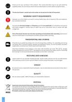
Thank you for your purchase of this product. This manual describes how to use and install the supplied product. Be sure that you have read and understood its contents before using the heater. The electrical heater's model and serial number are located on the label of the product. WARNING! SAFETY REQUIREMENTS Improper use of this heater can result in serious bodily injury due to hazards of fire and explosion, burn and electrical shock. Use only with electrical voltage and frequency specified on model label. Do not perform any service with heater plugged in. Serious injury or death may occur if personnel...
Open the catalog to page 2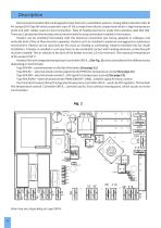
Descrip on Electrical duct heaters EKA are designed to heat fresh air in ven la on systems. Casing (EKA protec on class IP 44, except EKA Type NV which protec on class IP 30) is made from Aluzinc coated steel which is high temperature proof and with rubber seals for duct connec on. Tube of hea ng element is made from stainless steel AISI 304. There are 2 protec on thermostats and screw terminals for easy connec on installed in the heaters. Heaters can be installed horizontally with the electrical connec on box facing upwards or sideways and ver cally (only if the air flow direc on upwards). Heaters...
Open the catalog to page 4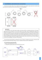
Installa on and electrical connec on Electrical duct heaters EKA can be installed horizontally in any posi on except electrical connec on box downward and ver cally (only if the air flow direc on upwards) (see Fig. 2). IMPORTANT: The installa on to the mains power supply may only be wired by a competent electrician. The power supply cable must be selected in the ra o with power of the heater. When installing these heaters, the standards and regula ons in force in your country must be followed strictly adhered to. Within the installa on an electrical isola on automa c circuit breaker (not included)...
Open the catalog to page 5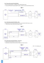
Fig. 4. Moun ng example EKA NIS/ESKM… *- External control signal (0…10VDC) is used in EKA NIS type heater. **- External PWM control signal ON/OFF: ON (6…24VDC) is used in EKA ESKM type heater. Fig. 5. Moun ng example EKA NV/NI…2NTC… *- Temperature set point knob and TR NTC10 are used in EKA NV 2NTC heater version. **- TR5K NTC10 is used in EKA NI 2NTC heater version. Fig. 6. Moun ng example EKA NV/NI… (Preheater) **- TR5K used only in EKA NI pre-heater version. *- Temperature set point knob used only in EKA NV pre-heater version.
Open the catalog to page 6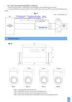
Fig. 7. Moun ng example EKA NIS/ESKM… (Preheater) *- External control signal 0…10VDC (from AHU if possible) is used in EKA NIS type pre-heater. **- External PWM control signal ON/OFF: ON 6…24VDC (from AHU if possible) is used in EKA ESKM type preheater. Type 1 – Standard EKA heater dimensions; Type 2 – EKA heater with external pressure relay dimensions; Type 3 – EKA heater with external cooling radiator dimensions; Type 4 – EKA heater with external cooling radiator and pressure relay di
Open the catalog to page 7
This declaration is in conformity with the requirements of the standards: and therefore complies with the essential requirements and provisions of the (LVD) 2014/35/EC, (EMC) 2014/30 EC, (RoHS) 2011/65/EU and REACH.
Open the catalog to page 9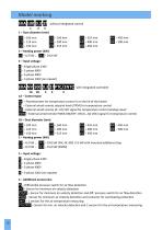
without integrated control PTC/2NTC with integrated controller NV - Potentiometer for temperature control is on the lid of the heater NJ - External wired remote setpoint knob (TR5K) for temperature control NlS- External wired remote (0...10) VDCsignal for temperature control (analog input) ESKM|- External wired remote PWM (ON/OFF: ON (6.24) VDC) signal for temperature control 1B - Duct diameter (mm) 0.3 -0,3 kW ... |24.0|- 24,0 kW (NV, NI, NIS) >15 kW with mounted additional step BUS-0,3 kW ... 150- 15,0 kW (ESKM) - Differential pressure switch for air flow detection _-Sensor for minimum air...
Open the catalog to page 10
Two overheat protection thermostats are installed in the electrical circular heater EKA. The first one with automatic reset, turns off the heating when the temperature reaches 50 °C and turns on when the temperature drops below 50 °C. The second with manual reset, turns off the heating when the temperature reaches 100 °C. In this case need to figure the cause of the overheating of the heater. Eliminate overheating cause, press „RESET" button on heaters cover. Additional overheating thermostat (with automatic reset) is installed in the EKA heater with ESKM to protect the ESKM controller. This...
Open the catalog to page 11
Descrip on of opera ng EKA NIS … Electrical duct heaters EKA NIS … are designed for the heaters power (0…100) % control by analog signal input (0…10) VDC. When the heater power supply is switched on, LED 6 on the controller (EKR-K…) PCB (see Fig. 1 on page 4) flashes every second. If controller turns on the hea ng depending on analog signal, LED 5 lights (see Fig. 1 on page 4). Descrip on of opera ng EKA NV … (PTC…PS) Electrical duct heaters EKA NV … (PTC…PS) are designed with integrated temperature control, PTC (air velocity), PS (air pressure) and temperature sensors, setpoint poten ometer knob...
Open the catalog to page 12
Descrip on of opera ng EKA NIS … (PTC…PS) * Electrical duct heaters EKA NIS … (PTC…PS) are designed for the heaters power (0…100) % control by analog signal input (0…10) VDC, with integrated PTC (air velocity) and PS (air pressure) sensors. When the heater power supply is switched on, controller (EKR-K…) is in prepara on mode for 30 seconds, LED 1 flashes once every 5 seconds. If air velocity is detected by PTC sensor (rapid LED 1 flashes when Min. 1,5 m/s is detected) and air pressure is greater than min 20kPA a er prepara on mode ends, LED 1 will start to flash once every second and controller...
Open the catalog to page 13
2.Control by the supply (TJ-K10K) and by the room (NTC10) air temperature sensor, when the first (1) switch of JP1 -(R37) (see Fig. 1 on page 4) is in posi on OFF. LED 6 flashes once per second. Setpoint temperature (15…30) °C. In this mode is preprogrammed the minimum (15°C) and the maximum (45°C) temperatures of supply air. The room air temperature sensor is mounted in the wired remote control panel TR5K NTC10. Depending on the opera ng mode there can be set the different desired (setpoint) air temperature by wired remote control panel TR5K NTC10. IMPORTANT: If failure appears, power supply must...
Open the catalog to page 14All Elta catalogs and technical brochures
 MULTIFLOW SEM
14 Pages
 RAPTOR SFB
8 Pages
 MARINE EMEC
10 Pages
 MULTIFloW MFB
28 Pages
 JetVent
12 Pages
 COMPACT POWERPLUS
12 Pages
 HERITAGE FCE/FCD
8 Pages
 MULTIFlow MFC
32 Pages
 Biflow Cylindrical/ Conical
4 Pages
 Smoke Vent
8 Pages
 Compact SCDA
7 Pages
 Compact SCPA
6 Pages
 Compact Range
15 Pages
 Window Wall Fan SAX
5 Pages
 Raptor Panel SRE
6 Pages
 Ezifit Thru-wall SEWE
5 Pages
 Ezifit in-wall SEIE
5 Pages
 Multiflow SMT
6 Pages
 Multiflow SMC
8 Pages
 Multiflow SMB
8 Pages
 Heat Recovery Units
5 Pages
 SWHR180 Heat Recovery Unit
4 Pages
 ZOO Fan SDF
6 Pages
 Ceiling Fan HCF
4 Pages
 Wall Fan HWFA
5 Pages
 Raptor Cooler SRC
5 Pages
 Pedestal Fan HPFA
5 Pages
 Viper SCC
11 Pages
 Twinflow STD
15 Pages
 Slim Qube SSQU-HT
6 Pages
 Singleflow SSD
15 Pages
 Quietflow SQS
15 Pages
 Quietflow SQT
15 Pages
 Quietflow SQT DCV
16 Pages
 Quietflow SQS DCV
16 Pages
 Quietflow Classic SQT
5 Pages
 Quietflow Classic SQS
5 Pages
 Qube SQU
6 Pages
 Qube SQU-HT
6 Pages
 Powerduct SPD
7 Pages
 Jetstream SJS
6 Pages
 Jetflow HIT
9 Pages
 Hideaway SH
11 Pages
 Biflow SB (CYL)
5 Pages
 Biflow SB (CON)
7 Pages
 Revolution SLC
14 Pages
 Raptor SPA
16 Pages
 Raptor SDA
18 Pages
 PowerPlus SPP
6 Pages
 Miniflow SAMF
6 Pages
 Compact SCP
8 Pages
 Compact PowerPlus SCPP
5 Pages
 SLCX Atex
7 Pages
 Raptor SFB Atex
5 Pages
 Twinflow STDR
14 Pages
 Twinflow STDR DCV
11 Pages
 Skyflow Viper SSC
12 Pages
 Skyflow SSRV
16 Pages
 Skyflow SSR
17 Pages
 Singleflow SSDR
13 Pages
 Singleflow SSDR DCV
10 Pages
 Miniflow SMF
5 Pages
 Heritage SCHT
7 Pages
 Heritage SGE
5 Pages
 Heritage SCH
6 Pages
 JETVENT INDUCTION
16 Pages
 Jetvent Axials
12 Pages
 BELT DRIVE BD
13 Pages
 LC/SC
LC/SC28 Pages
 Centrifugal JetVent Mixed
12 Pages
 JetVent Flanged
12 Pages
 ATEX Fans
4 Pages


- Metal fan
- Surface-mounted detector
- Commercial fan
- Indoor fan
- Mechanical ventilation unit
- White detector
- Commercial detector
- Programmable thermostat
- Ventilation controller
- Digital thermostat
- Extractor fan
- Wall-mounted ventilation controller
- Duct fan
- Industrial fan
- Domestic fan
- Industrial centrifugal fan
- Axial fan
- Wall-mount fan
- Commercial ventilation controller