
- Catalogs
- Dimplex, Geschäftsbereich der Glen Dimplex Deutsch
- Air-to-Water Heat Pump for Outdoor Installation

Air-to-Water Heat Pump for Outdoor Installation

Air-to-Water Heat Pump for Outdoor Installation
Compliance with local legal requirements is mandatory for operation and maintenance. The heat pump should not be tilted more than 45° during transport. Ensure no obstructions in the intake and exhaust areas. Avoid installation in depressions or courtyards to prevent re-circulation of cooled air. Electrical connections must adhere to VDE, EN, and IEC standards.
Designed for heating and potentially cooling of heating water. Suitable for monoenergetic and bivalent operation. Not intended for high heat demand during building drying. Operates by transferring heat from ambient air to heating water using a refrigerant cycle.
Main unit includes components like evaporator, compressor, and control box. Uses R410A refrigerant, which is non-flammable and ozone-friendly. Includes a heat pump manager for efficient control and monitoring.
Ensure proper setup of condensate drainage. Electrical and heating connections must follow specified guidelines. Proper setup is crucial for energy-efficient operation.
Regular checks by trained personnel are required. Cleaning of heat exchangers is essential to maintain efficiency. Troubleshooting guidelines are provided for common issues.
Follow specific procedures for safe decommissioning and disposal. Legal requirements for refrigerant handling must be observed.
The document outlines the specifications for the installation and operation of a heat pump system. It includes details on the external temperature sensor, which is provided with the heat pump unit and manager. The operation and handling of the heat pump manager are described in the accompanying user manual.
A remote control station is available as an optional accessory, offering the same operation and menu navigation as the heat pump manager. Connection is via an interface with an RJ 12 plug. The heat pump manager can be integrated into a building management system through additional interface cards, supporting Modbus, EIB, KNX, and Ethernet connections.
The heat pump must be transported with a maximum tilt of 45 degrees and should be moved using a pallet. The unit and transport pallet are secured with four anti-tip devices that must be removed. Installation requires a flat, smooth surface to ensure proper sound insulation and protection against small animals. The air outlet direction should be perpendicular to the main wind direction to facilitate defrosting. Specific installation conditions, such as elevated platforms or high wind loads, may require additional anti-tip measures.
Condensate must be drained frost-free, with the heat pump standing horizontally. The condensate pipe should have a minimum diameter of 50 mm and be frost-protected. Direct discharge into sewage treatment plants or pits is not allowed due to potential damage from aggressive vapors.
Heating connections are made inside the unit, with hoses leading downward. The heating system must be flushed before connection to remove debris. The electrical connection requires a 5-core cable, with specific requirements for phase sequence and overload protection. A screened communication cable connects the heat pump manager to the internal microcontroller.
Commissioning should be performed by authorized service personnel. All connections must be installed, and the heating circuit must be free of obstructions. The heat pump manager settings must be adjusted according to the user manual. The commissioning process involves ensuring water flow, selecting the "Automatic" mode, and gradually opening heating circuits.
To protect the paint, avoid leaning objects against the unit. The exterior can be cleaned with a damp cloth and standard cleaners, avoiding abrasive or acidic substances.
The document provides detailed technical information on the installation, operation, and maintenance of an air-to-water heat pump system. It covers specifications, intended use, operating principles, components, and installation guidelines.
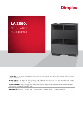
The heat pump is designed for heating and, depending on the model, cooling heating water. It is suitable for both new and existing heating systems and can operate in mono energy and bivalent modes. The system is not intended for high heat consumption scenarios, such as building drying, and is not compatible with frequency converters.
The heat pump extracts heat from the surrounding air using a fan and evaporator, transferring it to a refrigerant. An electrically driven compressor increases the heat's temperature, which is then transferred to the heating water. The system can also operate in reverse for cooling, where the heating water transfers heat to the refrigerant.
The main components include a fan, liquefier, compressor, evaporator, expansion valve, filter dryer, switch box, and dirt trap. The system uses the refrigerant R410A, which is CFC-free and non-combustible.
The heat pump must be installed on a level surface with adequate sound insulation and protection from small animals. It should be positioned to allow unrestricted defrosting of the evaporator. Condensate must be drained frost-free, and the system should be protected against frost if necessary.
Connections include the flow and return of the heating system, condensate drain, control cable, and power supply. The heating system must be flushed before connection to remove impurities. Electrical connections require a 5-core cable and appropriate circuit protection.
Optional accessories include a remote control and building management system connectivity via Modbus, EIB, KNX, or Ethernet. The heat pump manager controls and monitors the system based on temperature and safety systems.
During transport, the heat pump should not be tilted more than 45 degrees. It should be transported using a pallet and secured with transit bolts, which must be removed before installation.
Regular maintenance is necessary to ensure efficient operation. The system must be installed in compliance with local building regulations and should allow for easy access for maintenance.
Ensure the incoming supply has a clockwise rotating field with phase sequence L1, L2, L3. Incorrect wiring prevents the heat pump from starting, indicated by a warning on the heat pump manager display. The control voltage is supplied via the heat pump manager, requiring a 3-pole line as per electrical documentation. A shielded communication line connects the heat pump manager with the µPC2 in the heat pump, necessary for outdoor installations.
The demand sensor R2.2 (NTC 10) must be installed based on the hydraulics used. Without it, the second heat generator cannot be controlled if communication is interrupted. The return sensor R2 is active when the compressor runs and must remain connected.
Commissioning should be performed by an authorized technician. Before starting, ensure all connections are installed, valves are open, air paths are clear, and the fan rotates correctly. The heat pump manager settings must match the heating system's instructions. The water in the buffer tank must be at least 18°C. Follow a specific procedure to ensure proper commissioning, including closing consumer circuits, ensuring correct water flow, and gradually reopening heating circuit valves.
Avoid leaning objects against the device. Clean external parts with a damp cloth and avoid abrasive cleaners. Prevent sediment in the heat exchanger by ensuring a diffusion-resistant installation. Severe contamination requires cleaning by a technician using a 5% phosphoric or formic acid solution. The air system, including the evaporator and fan, should be cleaned before each heating period. Ensure proper drainage from the condensate tray.
Faults are indicated on the heat pump manager display. Consult the operating instructions for troubleshooting. Only authorized technicians should perform work on the heat pump.
Disconnect the heat pump from the power source and close all valves before removal. Trained personnel must dismantle the pump, adhering to environmental standards for material disposal, especially refrigerants and oils.
Models include LA 9S-TU, LA 12S-TU, and LA 18S-TU, all designed for outdoor installation with integrated thermal energy metering. Operating limits include heating water flow from 18°C to 60°C and air heating from -22°C to +35°C. Sound levels and dimensions are specified, with refrigerant type R410A used across models.
The document outlines the specifications for a heat pump system, including electrical connections, protection standards, and energy efficiency ratings. The system operates on a 3-phase 400 V supply with a control voltage of 230 V. It features a soft starter for current limiting and rotary field monitoring. The degree of protection is IP 24, and the system complies with European safety regulations.
Installation and operation procedures are detailed, emphasizing the importance of adhering to legal requirements and ensuring proper electrical connections. The document advises on the correct handling and installation angles during transport and the removal of transport wedges before commissioning.
The heat pump is designed to meet CE, DIN, and VDE standards, suitable for domestic environments. It is recommended to maintain a small temperature difference between the heating water and the heat source to optimize energy efficiency. Regular maintenance checks on the refrigerant seal are advised.
The heat pump is rated A++ for energy efficiency, with specific performance metrics provided for various temperature conditions. The document highlights the importance of clean heat exchangers for optimal performance.
Features include reverse circulation defrosting, frost protection, and a maximum operating pressure of 3.0 bar. The system is compatible with low-temperature heating systems like underfloor heating.
Performance levels are provided for different temperature scenarios, with detailed COP (Coefficient of Performance) values. The document notes that performance can be affected by factors such as defrosting capacity and heat exchanger cleanliness.
Legal and safety compliance is emphasized, with specific instructions for installation and operation to prevent hazards. The document advises on the correct magnetic field rotation and warns against improper installation locations.
Regular maintenance and cleaning are necessary to ensure efficient operation. Troubleshooting guidelines are provided for common issues, and it is advised that only qualified personnel perform repairs.
The document emphasizes the importance of a well-regulated heat pump manager for energy-efficient operation. Detailed instructions for the heat pump manager are available in the user manual.
2.1 Application Domain
The air/water heat pump is designed exclusively for heating or cooling water in heating systems, suitable for both existing and new installations. It supports mono-energetic and bivalent modes. A return water temperature above 18°C is necessary for optimal defrosting of the evaporator. The heat pump is not suitable for high heat demands like construction drying, which requires special equipment.
In heating mode, ambient air is drawn through the evaporator, cooling the air and transferring heat to the refrigerant. The compressor elevates the temperature, transferring heat to the heating water via the condenser. In cooling mode, the process is reversed. Key components include the evaporator, fan, compressor, and condenser.
3.1 Basic Unit with Electrical Box
The heat pump contains components like the fan, condenser, compressor, evaporator, and electrical box. The refrigerant circuit is sealed and contains R410A, a non-flammable refrigerant with no ozone depletion potential.
The included heat pump manager controls and monitors the heating system based on external temperature and safety devices. It comes with an external temperature sensor and necessary mounting materials.
Remote control and building management system integration are available as accessories, with options for Modbus, EIB, KNX, and Ethernet connections.
5 Transport
The heat pump should not exceed a 45° tilt during transport and should be moved on a pallet. Anti-tilt devices must be removed before installation.
The unit should be installed on a stable, flat surface, with sound insulation and protection against small animals. Proper spacing for maintenance and airflow must be maintained. Condensate drainage must be protected from freezing.
7.1 General Connections
Connections include heating circuits, condensate drainage, control lines, and power supply. The heating system must be flushed before connecting to the heat pump.
Heating connections are made inside the unit, with specific sizes provided in the device information. Proper water quality and flow rates must be maintained to prevent damage and ensure efficient operation.
1. Differential valves are recommended for surface heating systems with a maximum water flow of 1.3m³/h to prevent operational issues.
2. Anti-freeze protection is necessary for heat pump systems exposed to freezing conditions. Systems should be drained if not in use or during power outages.
1. Three lines/cables are required for the heat pump, including a 5-wire power cable, a control voltage line, and a shielded communication line.
2. Ensure correct phase order (L1, L2, L3) to avoid startup issues.
1. Commissioning should be performed by authorized service personnel.
2. Verify all connections and ensure proper airflow and water flow before starting.
3. Follow specific steps to gradually open heating circuits and maintain minimum return temperatures.
1. Regular cleaning of the heat exchanger and air components is necessary to prevent corrosion and maintain efficiency.
2. Use appropriate cleaning agents and follow safety guidelines when handling acids.
1. Faults are displayed on the heat pump manager screen. Refer to the user manual for troubleshooting steps.
2. Only qualified service personnel should perform repairs.
1. Ensure the system is powered off and valves are closed before dismantling.
2. Follow environmental regulations for the disposal of refrigerants and oils.
1. The heat pumps are designed for outdoor installation with specific power and efficiency ratings.
2. Electrical specifications include power supply requirements and protection measures.
3. The system includes features like defrosting and anti-freeze protection.
1. The heat pumps have varying capacities and performance coefficients depending on the model and conditions.
2. Energy efficiency classes are provided for different temperature ranges.
- Heat Pump Manager (N1): Manages the operation of the heat pump.
- External Wall Sensor (R1): Measures external wall temperature.
- Additional Return Flow Sensor (R2.1): Monitors return flow temperature.
- Hot Water Sensor (R3): Measures domestic hot water temperature.
- Temperature Sensor for Heating Circuit 2 (R5): Monitors temperature in the second heating circuit.
- Reversing Valve for Domestic Hot Water (YM18): Controls the flow direction of domestic hot water.
- The document certifies that the heat pumps comply with relevant EU directives, including the Low Voltage Directive (2014/35/EU), EMC Directive (2014/30/EU), and Pressure Equipment Directive (2014/68/EU).
- Compliance is subject to no modifications being made to the devices.
- Regulation (EU) No 813/2013 is applicable.
- Conformity assessment is conducted under Module A of the Pressure Equipment Directive.
- Includes standards such as EN 60335-1:2012, EN 55014-1:2006, EN 61000-3-2:2014, and others related to safety, electromagnetic compatibility, and performance.
- Glen Dimplex Deutschland GmbH, Am Goldenen Feld 18, D-95326 Kulmbach, Germany.
- Phone: +49 (0) 9221 709 565
- Website: www.dimplex.de
Catalog excerpts
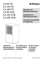
Montage- und Gebrauchsanweisung Installation and Operating Instruction Instruction d'installation et d'utilisation Air-to-Water Heat Pump for Outdoor Installation Pompe a chaleur air-eau pour installation exterieure Bestell-Nr. / Order no. / No de commande : 452168.66.01 DE / EN / FR ■ FD 9901
Open the catalog to page 1
Bitte sofort lesen Wichtige Hinweise Für den Betrieb und die Wartung einer Wärmepumpe sind die rechtlichen Anforderungen des Landes einzuhalten, in dem die Wärmepumpe betrieben wird. Je nach Kältemittelfüllmenge ist die Dichtheit der Wärmepumpe in regelmäßigen Abständen durch entsprechend geschultes Personal zu überprüfen und zu protokollieren. Vor der Inbetriebnahme ist die Transportsicherung zu entfernen. Der Ansaug- und Ausblasbereich darf nicht eingeengt oder zugestellt werden. Bei wandnaher Aufstellung sind bauphysikalische Beeinflussungen zu beachten. Im Ausblasfeld des Ventilators sollten...
Open the catalog to page 4
Energiesparende Handhabung der Wärmepumpe Mit dem Betrieb dieser Wärmepumpe tragen Sie zur Schonung der Umwelt bei. Die Voraussetzung für eine energiesparende Betriebsweise ist die richtige Auslegung der Wärmequellen- und Wärmenutzungsanlage. Besonders wichtig für die Effektivität einer Wärmepumpe ist es, die Temperaturdifferenz zwischen Heizwasser und Wärmequelle möglichst gering zu halten. Deshalb ist eine sorgfältige Auslegung der Wärmequelle und der Heizungsanlage dringend anzuraten. Eine um ein Kelvin (ein °C) höhere Temperaturdifferenz führt zu einer Steigerung des Stromverbrauches von...
Open the catalog to page 5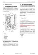
Für den Betrieb Ihrer (reversiblen) Luft/Wasser-Wärmepumpe ist der im Lieferumfang enthaltene Wärmepumpenmanager zu verwenden. Die Wärmepumpe enthält unten aufgeführte Bauteile. Der Kältekreis ist „hermetisch geschlossen“ und enthält das vom Kyoto-Protokoll erfasste fluorierte Kältemittel R410A. Angaben zum GWP-Wert und CO2-Äquivalent des Kältemittels finden sich im Kapitel Geräteinformation. Es ist FCKW-frei, baut kein Ozon ab und ist nicht brennbar. Der Wärmepumpenmanager ist ein komfortables elektronisches Regel- und Steuergerät. Er steuert und überwacht die gesamte Heizungsanlage in Abhängigkeit...
Open the catalog to page 6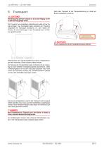
Nach dem Transport ist die Transportsicherung im Gerät am Boden beidseitig zu entfernen. Die Wärmepumpe darf beim Transport nur bis zu einer Neigung von 45° (in jeder Richtung) gekippt werden. Der Transport zum endgültigen Aufstellungsort sollte mit der Palette erfolgen. Das Grundgerät bietet einerseits die Transportmöglichkeit mit Hubwagen, Sackkarre o.Ä., oder mittels 3/4" Rohren, die durch Bohrungen in der Grundplatte bzw. im Rahmen geführt werden. Transportsicherung entfernen/einschrauben Vor der Inbetriebnahme ist die Transportsicherung zu entfernen. Wärmepumpe und Transportpalette sind...
Open the catalog to page 7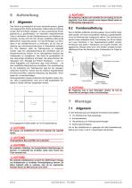
6 Aufstellung 6.1 Allgemein Das Gerat ist grundsatzlich auf einer dauerhaft ebenen, glatten und waagerechten Flache aufzustellen. Dabei sollte der Rahmen rundum dicht am Boden anliegen, um eine ausreichende Schall-abdichtung zu gewahrleisten, ein Auskuhlen wasserfuhrender Teile zu verhindern und den Gerateinnenraum vor Kleintieren zu schutzen. Ist dies nicht der Fall, konnen zusatzliche dammende MaUnahmen notwendig werden. Um das Eindringen von Kleintieren in den Gerateinnenraum zu verhindern, ist z.B. eine ab-dichtung des Anschlussdurchbruches im Bodenblech erforder-lich. Des Weiteren sollte...
Open the catalog to page 8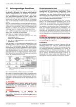
7.2 Heizungsseitiger Anschluss Die heizungsseitigen Anschlusse an der Warmepumpe sind im Gerateinneren herzustellen. Die jeweiligen AnschlussgroBen sind den Gerateinformationen zu entnehmen. Die anzuschlie-Benden Schlauche werden nach unten aus dem Gerat gefuhrt. Dazu ist ein Wellflex-Schlauchset als Zubehor erhaltlich. Seitli-che Durchfuhrungen im Rahmen ermoglichen ebenfalls eine Lei-tungsfuhrung zur Seite. Beim Anschluss an die Warmepumpe muss an den Ubergangen mit einem Schlussel gegengehalten werden. Bevor die heizwasserseitigen Anschlusse der Warmepumpe er-folgen, muss die Heizungsanlage...
Open the catalog to page 9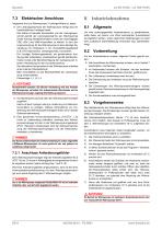
Elektrischer Anschluss Insgesamt sind zur Wärmepumpe 3 Leitungen/Kabel zu legen: Der Leistungsanschluss der Wärmepumpe erfolgt über ein handelsübliches 5-adriges Kabel. Das Kabel ist bauseits beizustellen und der Leitungsquerschnitt gemäß der Leistungsaufnahme der Wärmepumpe (siehe Anhang Geräteinformation) sowie der einschlägigen VDE- (EN-) und VNB-Vorschriften zu wählen. In der Leistungsversorgung für die Wärmepumpe ist eine allpolige Abschaltung mit mindestens 3 mm Kontaktöffnungsabstand (z.B. EVU-Sperrschütz, Leistungsschütz) vorzusehen. Ein 3-poliger Sicherungsautomat, mit gemeinsamer...
Open the catalog to page 10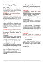
Reinigung / Pflege Vermeiden Sie zum Schutz des Lackes das Anlehnen und Ablegen von Gegenständen am und auf dem Gerät. Die Außenteile der Wärmepumpe können mit einem feuchten Tuch und mit handelsüblichen Reinigern abgewischt werden. Reinigung Luftseite Verdampfer, Lüfter und Kondensatablauf sind vor der Heizperiode von Verunreinigungen (Blätter, Zweige usw.) zu reinigen. Dazu ist die Wärmepumpe, wie im Kapitel 7.1 beschrieben, zu öffnen. Vor Öffnen des Gerätes ist sicherzustellen, dass alle Stromkreise spannungsfrei geschaltet sind. Verwenden Sie nie sand-, soda-, säure- oder chloridhaltige Putzmittel,...
Open the catalog to page 11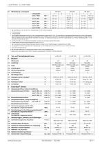
Wärmeleistung / Leistungszahl 1. Bei Lufttemperaturen von -22°C bis -5°C, Vorlauftemperatur von 45°C bis 60°C steigend. 2. 2 Verdichterbetrieb 3. 1 Verdichterbetrieb 4. Diese Angaben charakterisieren die Größe und die Leistungsfähigkeit der Anlage nach EN 14511. Für wirtschaftliche und energetische Betrachtungen sind weitere Einflussgrößen, insbesondere Abtauverhalten und Regelung zu berücksichtigen. Diese Angaben werden ausschließlich mit sauberen Wärmeübertragern erreicht. Hinweise zur Pflege, Inbetriebnahme und Betrieb sind den entsprechenden Abschnitten der Montage- und Gebrauchsanweisung...
Open the catalog to page 13All Dimplex, Geschäftsbereich der Glen Dimplex Deutsch catalogs and technical brochures


Archived catalogs
 DHW 300
2 Pages
 LA 60S-TU(R)
4 Pages
 SI 22TU
6 Pages
 Heat pump
34 Pages
 LI 24TES
10 Pages
 Highlight brochure 2023
36 Pages
 LA 0712BWC
2 Pages
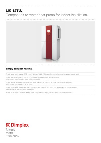 LIK12TU
2 Pages
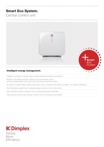 Smart Eco System
2 Pages
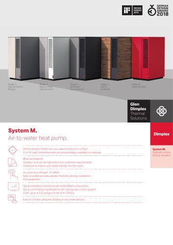 System M.
2 Pages
 Domestic hot water
28 Pages
 Plus Magazine
100 Pages
 System M
15 Pages
 Heat Pump Assortment 2017
25 Pages
 Intelligent Quantum
4 Pages
 Dimplex more heatpumps
5 Pages
 LA_STU heatpump
6 Pages
 Factsheet SITU
2 Pages
 SI 35TUR/SI 70TUR
2 Pages
 Splydro
2 Pages
 Heat Pumps
15 Pages
 Dimplex Product Range 2017
77 Pages
 System C.
9 Pages
 BK infrared heaters
2 Pages
 Innovations for 2013
11 Pages
 System Zero
11 Pages
 DHW 400+.
2 Pages
 M Flex Air
2 Pages
 Dimplex Heat Pumps 2014
31 Pages
 NEWS 2013
11 Pages
 Dimplex Heat Pumps
40 Pages
 Product Range Overview 2013
122 Pages
 NEW (innovations 2011)
7 Pages
 BA series patio radiators
2 Pages
 Product range
118 Pages













- Residential heat pump
- Air source heat pump
- Outdoor heat pump
- Industrial water heater
- Mechanical ventilation unit
- Vertical water heater
- Inverter heat pump
- Energy rating heat pump
- Electric water heater
- Smart heat pump
- Ventilation unit
- Split heat pump
- Commercial heat pump
- Monobloc heat pump
- Class A+++ heat pump
- Residential ventilation unit
- Home ventilation unit
- Reversible heat pump